DT-7000 OPERATOR’S MANUAL Software Version 1.01 15222 Del Amo Ave. Tustin, California 92780 714.546.0147 Fax 714.571.3945 Toll-free Telephone 800.888.0077 www.vitalcom.
Copyright ©2000 VitalCom Inc. All rights reserved. 15222 Del Amo Avenue, Tustin, California 92780 Limited Software License and Equipment Use All software licensed by VitalCom to Customers is licensed under a limited, nontransferable license and VitalCom reserves all rights not expressly granted. The software license permits the customer to use the software only on equipment purchased from VitalCom.
TABLE OF CONTENTS Introduction........................................................................................................................................ 5 System Overview ...................................................................................................................... Equipment Site Selection/Location........................................................................................... Clinical Use and Responsibility ..................................................
This page is intentionally left blank. iv DT-7000 Operator’s Manual, Revision A All information contained herein is subject to the rights and restrictions on the title page.
INTRODUCTION INTRODUCTION System Overview Wireless Medical Telemetry Services (WMTS) Remote Transceivers provide the link between the patient and the Central Station through the newly approved 608 - 614 MHz Medical Telemetry frequency band. The ambulatory and bedside device transceivers communicate data to the Central Station through the Access Point transceiver. In addition, the transceivers are capable of receiving control commands for self-use or connection transfer.
INTRODUCTION Clinical Use and Responsibility CAUTION: United States Federal law restricts this device to sale by, or on the order of, a physician or properly licensed practitioner. The PatientNet System provides the technology to monitor cardiac rhythms, vital signs, and equipment alarms for patients with various levels of acuity in multiple patient care settings. The monitoring system does not replace physicians, caregivers or system operators.
INTRODUCTION Notes 1. This equipment has been tested and found to comply with the limits for a CLASS B digital device, pursuant to Part 15 of the FCC Rules. These limits are designed to provide reasonable protection against harmful interference in a residential installation.
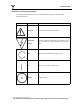
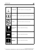
INTRODUCTION Definitions of International Symbols The following table defines the international symbols that appear on the PatientNet Wireless NetworkTM Symbol Name Definition Attention Consult accompanying documents Hazardous Voltage Caution: Dangerous Voltages. Do not remove cover or back. Refer servicing to qualified service personnel.
INTRODUCTION 10 Earth Ground Functional. The device is electrically grounded.
INTRODUCTION Humidity Limitation Storage / Transportation Packaging IPX7 IPX7 This device can be immersed in 1m of water for 30min. IPX1 IPX1 V Volts A Amperes VA Volt Amperes Hz Hertz This device is protected against vertically falling water drops.
USE AND MAINTENANCE USE AND MAINTENANCE The DT-7000 and DT-7001 send data and alarm information from bedside monitors and ventilators to the Central Station. The transceivers support the bedside monitors shown in “Appendix A” on page 167.
USE AND MAINTENANCE Attendant Present / Procedure Alarm Silence (PAS) Unlock Button The Attendant Present push button has three functions. Each function is initiated based on how long the button is pressed. 1. Exiting the Standby Mode DT-7001 - If the transceiver is powered by battery only, then pressing the Attendant Present button will take the transceiver out of Standby Mode and all LEDs will illuminate for a few seconds.
USE AND MAINTENANCE Procedure Alarm Silence (PAS) Button Depressing the PAS button, while the PAS Status Indicator LED is flashing, informs the clinicians at the Central Station area that the attending nurse will be performing a procedure to the patient that may cause inadvertent false alarms at the Central Station (i.e. changing lead wires, electrodes, etc.) Once the PAS button is pressed, the following events occur at the Central Station. 1.
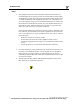
USE AND MAINTENANCE External Serial Devices (I/O) Ports 3 and 4* Power Connector Bottom View External Serial Devices (I/O) Ports 1 and 2* Procedure Alarm Silence (PAS) button External Serial Devices (I/O) Ports Status Indicators* Nurse Call button Attendant Present and Power buttons RF, Low Battery, and Power Adapter Indicators PAS Status Indica- Remote Record button Front View Fig. 1.
USE AND MAINTENANCE LED Indicators Function Once the transceivers exit Standby Mode, either by pressing the Attendant Present or Power buttons, all LED indicators are illuminated for a brief period. After the specified time period, only those LEDs displaying positive (or negative) transceiver functions, as described in each section below, remain illuminated. Procedure Alarm Silence Status Indicator The Procedure Alarm Silence Status Indicator is illuminated when the PAS function is active.
USE AND MAINTENANCE Cleaning This section provides cleaning and maintenance instructions for DT-7000 and DT7001 transceivers. Read and follow all precautions when cleaning transceivers. WARNING: VitalCom makes no claims concerning the sterilization of the DT-4500 Ambulatory, DT-7000, and DT-7001 Instrument Transceivers. CAUTION: Do not gas sterilize or AUTOCLAVE any part of the monitoring system, transmitters, or transceivers. Note: DO NOT use abrasive cleaners. Cleaning the Chassis 1.
USE AND MAINTENANCE Connecting to the Bedside Monitor See Figure 1 on page 15 for an image of the DT-7000/DT-7001 controls and LED indicators. Note: Before the transceiver is connected to the bedside monitor, the system administrator must program it with the bedside device specific software module. 1. Attach the transceiver to the bedside monitor by sliding the Device Hook over the Mounting Disk until the transceiver snaps into place.
SPECIFICATIONS SPECIFICATIONS Specifications are approximate and may change with the actual unit shipped. Call VitalCom Customer Support 800.955.2424 if precise specifications are required. The DT-7000 is an externally powered Class 1 device and is suitable for continuous operation. The DT-7001 is an internally powered Class 1 device and is suitable for continuous operation. Both devices are intended for non-patient connection use.
STATEMENT OF COMPLIANCE STATEMENT OF COMPLIANCE UL Classification DT-700x WITH RESPECT TO ELECTRIC SHOCK, FIRE, AND MECHANICAL HAZARDS ONLY IN ACCORDANCE WITH UL2601-1/CAN/CSA C22.2 NO. 601.1 79VK The DT-7000/7001 transceiver is classified in accordance with UL 2601-1 and IPX1 (according to IEC 529-1989) on non-patient equipment. The DT-7000/7001 has been designed to withstand the effects of EMI and meets the EMC requirements of EN60601-1-2 (April 1993) and CISPR 11.