
User`s guide


CY7C66013
C
CY7C66113
C
Document #: 38-08024 Rev. *B Page 39 of 61
18.3 Hub Downstream Ports Status and Control
Data transfer on hub downstream ports is controlled according to the bit settings of the Hub Downstream Ports Control Register
(Figure 18-4). Each downstream port is controlled by two bits, as defined in Table 18-1 below. The Hub Downstream Ports Control
Register is cleared upon reset or bus reset, and the reset state is the state for normal USB traffic. Any downstream port being
forced must be marked as disabled (Figure 18-3) for proper operation of the hub repeater.
Firmware should use this register for driving bus reset and resume signaling to downstream ports. Controlling the port pins through
this register uses standard USB edge rate control according to the speed of the port, set in the Hub Port Speed Register.
The downstream USB ports are designed for connection of USB devices, but can also serve as output ports under firmware
control. This allows unused USB ports to be used for functions such as driving LEDs or providing additional input signals. Pulling
up these pins to voltages above V
REF
may cause current flow into the pin.
This register is not reset by bus reset. These bits must be cleared before going into suspend.
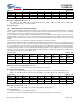
Hub Downstream Ports Control Register ADDRESS 0x4B
An alternate means of forcing the downstream ports is through the Hub Ports Force Low Register (Figure 18-5). With these
registers the pins of the downstream ports can be individually forced LOW, or left unforced. Unlike the Hub Downstream Ports
Control Register, above, the Force Low Register does not produce standard USB edge rate control on the forced pins. However,
this register allows downstream port pins to be held LOW in suspend. This register can be used to drive SE0 on all downstream
ports when unconfigured, as required in the USB 1.1 specification.
Hub Ports Force Low ADDRESS 0x51
The data state of downstream ports can be read through the HUB Ports SE0 Status Register (Figure 18-6) and the Hub Ports
Data Register (Figure 18-7). The data read from the Hub Ports Data Register is the differential data only and is independent of
the settings of the Hub Ports Speed Register (Figure 18-2). When the SE0 condition is sensed on a downstream port, the
corresponding bits of the Hub Ports Data Register hold the last differential data state before the SE0. Hub Ports SE0 Status
Register and Hub Ports Data Register are cleared upon reset or bus reset.
Hub Ports SE0 Status ADDRESS 0x4F
Bit [0..3]: Port x SE0 Status (where x = 1..4)
Set to 1 if a SE0 is output on the Port x bus; Set to 0 if a Non-SE0 is output on the Port x bus.
Bit [7..4]: Reserved.
Bit #76543210
Bit Name Port 4
Control Bit 1
Port 4
Control Bit 0
Port 3
Control Bit 1
Port 3
Control Bit 0
Port 2
Control Bit 1
Port 2
Control Bit 0
Port 1
Control Bit 1
Port 1
Control Bit 0
Read/Write R/W R/W R/W R/W R/W R/W R/W R/W
Reset 00000000
Figure 18-4. Hub Downstream Ports Control Register
Table 18-1. Control Bit Definition for Downstream Ports
Control Bits
Control ActionBit1 Bit 0
0 0 Not Forcing (Normal USB Function)
0 1 Force Differential ‘1’ (D+ HIGH, D– LOW)
1 0 Force Differential ‘0’ (D+ LOW, D– HIGH)
1 1 Force SE0 state
Bit #76543210
Bit Name Force Low
D+[4]
Force Low
D-[4]
Force Low
D+[3]
Force Low
D–[3]
Force Low
D+[2]
Force Low
D–[2]
Force Low
D+[1]
Force Low
D–[1]
Read/Write R/W R/W R/W R/W R/W R/W R/W R/W
Reset 0 0 000000
Figure 18-5. Hub Ports Force Low Register
Bit #76543210
Bit Name Reserved Reserved Reserved Reserved Port 4
SE0 Status
Port 3
SE0 Status
Port 2
SE0 Status
Port 1
SE0 Status
Read/Write - - - - R R R R
Reset 0 0 0 0 0 0 0 0
Figure 18-6. Hub Ports SE0 Status Register