CY7C66013C CY7C66113C Full-Speed USB (12 Mbps) Peripheral Controller with Integrated Hub Full-Speed USB (12 Mbps) Peripheral Controller with Integrated Hub Cypress Semiconductor Corporation Document #: 38-08024 Rev.
CY7C66013C CY7C66113C TABLE OF CONTENTS 1.0 FEATURES ......................................................................................................................................6 2.0 FUNCTIONAL OVERVIEW .............................................................................................................7 2.1 GPIO ..........................................................................................................................................7 2.2 DAC ...............................
CY7C66013C CY7C66113C 16.0 INTERRUPTS ..............................................................................................................................31 16.1 Interrupt Vectors .....................................................................................................................33 16.2 Interrupt Latency ....................................................................................................................34 16.3 USB Bus Reset Interrupt ...............................
CY7C66013C CY7C66113C LIST OF FIGURES Figure Figure Figure Figure Figure Figure Figure Figure Figure Figure Figure Figure Figure Figure Figure Figure Figure Figure Figure Figure Figure Figure Figure Figure Figure Figure Figure Figure Figure Figure Figure Figure Figure Figure Figure Figure Figure Figure Figure Figure Figure Figure Figure Figure Figure Figure Figure Figure Figure Figure Figure Figure Figure 3-1. CY7C66113C 56-pin QFN Pin Assignment ............................................................
CY7C66013C CY7C66113C LIST OF TABLES Table 3-1. Pad Coordinates in microns (0,0) to bond pad centers .......................................................13 Table 4-1. Pin Assignments .................................................................................................................14 Table 4-2. I/O Register Summary ........................................................................................................14 Table 4-3. Instruction Set Summary ....................................
CY7C66013C CY7C66113C 1.
CY7C66013C CY7C66113C 2.0 Functional Overview The CY7C66013C and CY7C66113C are compound devices with a full-speed USB microcontroller in combination with a USB hub. Each device is well-suited for combination peripheral functions with hubs, such as a keyboard hub function. The eight-bit one-time-programmable microcontroller with a 12-Mbps USB Hub supports as many as four downstream ports. 2.1 GPIO The CY7C66013C features 29 GPIO pins to support USB and other applications.
CY7C66013C CY7C66113C 2.8 Interrupts The microcontroller supports eleven maskable interrupts in the vectored interrupt controller. Interrupt sources include the 128-µs (bit 6) and 1.024-ms (bit 9) outputs from the free-running timer, five USB endpoints, the USB hub, the DAC port, the GPIO ports, and the I2C-compatible master mode interface. The timer bits cause an interrupt (if enabled) when the bit toggles from LOW ‘0’ to HIGH ‘1.
CY7C66013C CY7C66113C Logic Block Diagram External 6-MHz crystal USB Transceiver D+[0] Upstream D–[0] USB Port PLL USB Transceiver D+[1] D–[1] USB Transceiver D+[2] D–[2] USB SIE USB Transceiver D+[3] D–[3] Interrupt Controller USB Transceiver D+[4] D–[4] 48 MHz Clock Divider 12-MHz 8-bit CPU 12 MHz Repeater RAM 256 byte 8-bit Bus PROM 8 KB Downstream USB Ports 6 MHz 12-bit Timer Watchdog Timer Power-On Reset GPIO PORT 0 P0[0] GPIO PORT 1 P1[0] GPIO/ HAPI PORT 2 Power management
CY7C66013C CY7C66113C 3.
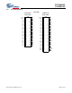
CY7C66013C CY7C66113C D+[0] P3[1] P1[7] P1[5] P1[3] Vref XTALIN XTALOUT Vcc P1[1] P1[0] P1[2] P1[4] P1[6] 56 55 54 53 52 51 50 49 48 47 46 45 44 43 D-[0] 1 42 P3[0] P3[3] 2 41 D–[3] GND 3 40 D+[3] P3[5] 4 39 P3[2] D+[1] 5 38 P3[4] D–[1] 6 37 D–[4] P2[1] 7 36 D+[4] D+[2] 8 35 P3[6] D–[2] 9 34 P2[0] P2[3] 10 33 P2[2] P2[5] 11 32 GND P2[7] 12 31 P2[4] DAC[7] 13 30 P2[6] P0[7] 14 29 DAC[0] CY7C66113C 56-pin QFN 15 16 17 18
CY7C66013C CY7C66113C (3398, 4194) Cypress Logo Pin 1 Pin 60 Pin 15 Pin 30 Pin 45 (0,0) DIE STEP: 3398 x 4194 microns Die Size: 3322 x 4129 microns Die Thickness: 14 mils = 355.6 microns Pad Size: 80 x 80 microns Figure 3-2. CY7C66113C DIE Document #: 38-08024 Rev.
CY7C66013C CY7C66113C Table 3-1. Pad Coordinates in microns (0,0) to bond pad centers Pad # Pin Name X Y Pad # Pin Name X Y 1 XtalOut 1274.2 3588.8 37 DAC6 2000.6 210.6 2 XtalIn 1132.8 3588.8 38 DAC4 2103.6 210.6 3 Vref 889.85 3588.8 39 DAC2 2206.6 210.6 4 Port11b 684.65 3588.8 40 Port06 2308.4 210.6 5 Port13 581.65 3588.8 41 Port04 2411.4 210.6 6 Port15 478.65 3588.8 42 Port02 2514.4 210.6 7 Vss 375.65 3588.8 43 Port00 2617.4 210.
CY7C66013C CY7C66113C 4.0 Product Summary Tables 4.1 Pin Assignments Table 4-1. Pin Assignments Name I/O D+[0], D–[0] I/O 8, 9 56, 1 8, 9 Upstream port, USB differential data. D+[1], D–[1] I/O 12, 13 5, 6 13, 14 Downstream port 1, USB differential data. D+[2], D–[2] I/O 15, 16 8, 9 16, 17 Downstream port 2, USB differential data. D+[3], D–[3] I/O 40, 41 40, 41 48, 49 Downstream port 3, USB differential data.
CY7C66013C CY7C66113C Table 4-2.
CY7C66013C CY7C66113C 4.3 Instruction Set Summary Refer to the CYASM Assembler User’s Guide for more details. Table 4-3.
CY7C66013C CY7C66113C 5.0 5.1 Programming Model 14-bit Program Counter (PC) The 14-bit Program Counter (PC) allows access to up to 8 KB of PROM available with the CY7C66x13C architecture. The top 32 bytes of the ROM in the 8K part are reserved for testing purposes. The program counter is cleared during reset, such that the first instruction executed after a reset is at address 0x0000h. Typically, this is a jump instruction to a reset handler that initializes the application (see Section 16.
CY7C66013C CY7C66113C 5.1.1 Program Memory Organization after reset Address 14-bit PC 0x0000 Program execution begins here after a reset 0x0002 USB Bus Reset interrupt vector 0x0004 128-µs timer interrupt vector 0x0006 1.
CY7C66013C CY7C66113C 5.2 8-bit Accumulator (A) The accumulator is the general-purpose register for the microcontroller. 5.3 8-bit Temporary Register (X) The “X” register is available to the firmware for temporary storage of intermediate results. The microcontroller can perform indexed operations based on the value in X. Refer to Section 5.6.3 for additional information. 5.
CY7C66013C CY7C66113C For USB applications, the firmware should set the DSP to an appropriate location to avoid a memory conflict with RAM dedicated to USB FIFOs. The memory requirements for the USB endpoints are described in Section 19.2. Example assembly instructions to do this with two device addresses (FIFOs begin at 0xD8) are shown below: MOV A,20h; Move 20 hex into Accumulator (must be D8h or less) SWAP A,DSP; swap accumulator value into DSP register. 5.
CY7C66013C CY7C66113C 2 cm). A 6-MHz fundamental frequency parallel resonant crystal can be connected to these pins to provide a reference frequency for the internal PLL. The two internal 30-pF load caps appear in series to the external crystal and would be equivalent to a 15-pF load. Therefore, the crystal must have a required load capacitance of about 15–18 pF.
CY7C66013C CY7C66113C The USB transmitter is disabled by a WDR because the USB Device Address Registers are cleared (see Section 19.1). Otherwise, the USB Controller would respond to all address 0 transactions. It is possible for the WDR bit of the Processor Status and Control Register (0xFF) to be set following a POR event. If a firmware interrogates the Processor Status and Control Register for a set condition on the WDR bit, the WDR bit should be ignored if the POR (bit 3 of register 0xFF) bit is set.
CY7C66013C CY7C66113C There are up to 31 GPIO pins (P0[7:0], P1[7:0], P2[7:0], and P3[6:0]) for the hardware interface. The number of GPIO pins changes based on the package type of the chip. Each port can be configured as inputs with internal pull-ups, open drain outputs, or traditional CMOS outputs. Port 3 offers a higher current drive, with typical current sink capability of 12 mA. The data for each GPIO port is accessible through the data registers.
CY7C66013C CY7C66113C As shown in Table 9-1 below, a positive polarity on an input pin represents a rising edge interrupt (LOW to HIGH), and a negative polarity on an input pin represents a falling edge interrupt (HIGH to LOW).
CY7C66013C CY7C66113C Port 1 Interrupt Enable ADDRESS 0x05 Bit # 7 6 5 4 3 2 1 0 Bit Name P1.7 Intr Enable P1.6 Intr Enable P1.5 Intr Enable P1.4 Intr Enable P1.3 Intr Enable P1.2 Intr Enable P1.1 Intr Enable P1.0 Intr Enable Read/Write W W W W W W W W Reset 0 0 0 0 0 0 0 0 Figure 9-8. Port 1 Interrupt Enable Port 2 Interrupt Enable Bit # 7 6 5 4 3 2 1 ADDRESS 0x06 0 P2.6 Intr Enable P2.5 Intr Enable P2.4 Intr Enable P2.3 Intr Enable P2.2 Intr Enable P2.
CY7C66013C CY7C66113C are set to ‘0’ when the device is suspended, that DAC input will float. The floating pin could result in excessive current consumption by the device, unless an external load places the pin in a deterministic state. DAC Port Data Bit # 7 6 5 4 3 2 ADDRESS 0x30 0 1 Bit Name DAC[7] DAC[6] DAC[5] DAC[4] DAC[3] DAC[2] DAC[1] DAC[0] Read/Write R/W R/W R/W R/W R/W R/W R/W R/W Reset 1 1 1 1 1 1 1 1 Figure 10-2. DAC Port Data Bit [1..
CY7C66013C CY7C66113C Bit [7..0]: Polarity bit x (x= 0..7) 1= Selects positive polarity (rising edge) that causes an interrupt (if enabled); 0 = Selects negative polarity (falling edge) that causes an interrupt (if enabled). 11.0 12-bit Free-running Timer The 12-bit timer operates with a 1-µs tick, provides two interrupts (128 µs and 1.024 ms) and allows the firmware to directly time events that are up to 4 ms in duration. The lower eight bits of the timer can be read directly by the firmware.
CY7C66013C CY7C66113C Bits [7,1:0] of the HAPI/I2C Configuration Register control the pin out configuration of the HAPI and I2C-compatible interfaces. Bits [5:2] are used in HAPI mode only, and are described in Section 14.0. Table 12-1 shows the HAPI port configurations, and Table 12-2 shows I2C pin location configuration options. These I2C-compatible options exist due to pin limitations in certain packages, and to allow simultaneous HAPI and I2C-compatible operation.
CY7C66013C CY7C66113C The I2C Status and Control register bits are defined in Table 13-1, with a more detailed description following. Table 13-1. I2C Status and Control Register Bit Definitions Bit Name Description 0 I2C Enable When set to ‘1’, the I2C-compatible function is enabled. When cleared, I2C GPIO pins operate normally. 1 Received Stop Reads 1 only in slave receive mode, when I2C Stop bit detected (unless firmware did not ACK the last transaction).
CY7C66013C CY7C66113C Bit 1: Receive Stop This bit is set when the slave is in receive mode and detects a stop bit on the bus. The Receive Stop bit is not set if the firmware terminates the I2C transaction by not acknowledging the previous byte transmitted on the I2C-compatible bus, e.g. in receive mode if firmware sets the Continue bit and clears the ACK bit. Bit 0: I2C Enable Set this bit to override GPIO definition with I2C-compatible function on the two I2C-compatible pins.
CY7C66013C CY7C66113C 15.0 Processor Status and Control Register Processor Status and Control Bit # 7 6 5 4 3 2 1 ADDRESS 0xFF 0 Bit Name IRQ Pending Watchdog Reset USB Bus Reset Interrupt Power-On Reset Suspend Interrupt Enable Sense Reserved Run Read/Write R R/W R/W R/W R/W R R/W R/W Reset 0 0 0 1 0 0 0 1 Figure 15-1. Processor Status and Control Register Bit 0: Run This bit is manipulated by the HALT instruction.
CY7C66013C CY7C66113C Global Interrupt Enable Register Bit # Bit Name ADDRESS 0X20 7 6 5 4 3 2 1 0 Reserved I2C GPIO Interrupt Enable DAC Interrupt Enable USB Hub Interrupt Enable 1.024-ms Interrupt Enable 128-µs Interrupt Enable USB Bus RST Interrupt Enable Interrupt Enable Read/Write - R/W R/W R/W R/W R/W R/W R/W Reset - 0 0 0 0 0 0 0 Figure 16-1.
CY7C66013C CY7C66113C When servicing an interrupt, the hardware does the following: 1. Disables all interrupts by clearing the Global Interrupt Enable bit in the CPU (the state of this bit can be read at Bit 2 of the Processor Status and Control Register, Figure 15-1). 2. Clears the flip-flop of the current interrupt. 3. Generates an automatic CALL instruction to the ROM address associated with the interrupt being serviced (i.e., the Interrupt Vector, see Section 16.1).
CY7C66013C CY7C66113C Table 16-1. Interrupt Vector Assignments Interrupt Vector Number ROM Address Function Not Applicable 0x0000 Execution after Reset begins here 1 0x0002 USB Bus Reset interrupt 2 0x0004 128-µs timer interrupt 3 0x0006 1.
CY7C66013C CY7C66113C the transaction (e.g., on the host’s ACK during an IN, or on the device ACK during on OUT). If no ACK is received during an IN transaction, no interrupt is generated. 16.6 USB Hub Interrupt A USB hub interrupt is generated by the hardware after a connect/disconnect change, babble, or a resume event is detected by the USB repeater hardware. The babble and resume events are additionally gated by the corresponding bits of the Hub Port Enable Register (Figure 18-3).
CY7C66013C CY7C66113C I2C Interrupt 16.9 2 The I C interrupt occurs after various events on the I2C-compatible bus to signal the need for firmware interaction. This generally involves reading the I2C Status and Control Register (Figure 13-2) to determine the cause of the interrupt, loading/reading the I2C Data Register as appropriate, and finally writing the Processor Status and Control Register (Figure 15-1) to initiate the subsequent transaction.
CY7C66013C CY7C66113C which (if any) of the downstream ports need to be enumerated. The following is a brief summary of the typical enumeration process of the CY7C66x13C by the USB host. For a detailed description of the enumeration process, refer to the USB specification. In this description, “Firmware” refers to embedded firmware in the CY7C66x13C controller. 1. The host computer sends a SETUP packet followed by a DATA packet to USB address 0 requesting the Device descriptor. 2.
CY7C66013C CY7C66113C Hub Ports Connect Status Bit # 7 6 5 4 3 2 1 Bit Name Reserved Reserved Reserved Port 4 Connect Status Port 3 Connect Status Port 2 Connect Status Port 1 Connect Status Reserved ADDRESS 0x48 0 Read/Write R/W R/W R/W R/W R/W R/W R/W R/W Reset 0 0 0 0 0 0 0 0 Figure 18-1. Hub Ports Connect Status Bit [0..3]: Port x Connect Status (where x = 1..4) When set to 1, Port x is connected; When set to 0, Port x is disconnected. Bit [7..4]: Reserved.
CY7C66013C CY7C66113C 18.3 Hub Downstream Ports Status and Control Data transfer on hub downstream ports is controlled according to the bit settings of the Hub Downstream Ports Control Register (Figure 18-4). Each downstream port is controlled by two bits, as defined in Table 18-1 below. The Hub Downstream Ports Control Register is cleared upon reset or bus reset, and the reset state is the state for normal USB traffic.
CY7C66013C CY7C66113C Hub Ports Data Bit # 7 6 5 4 3 2 1 ADDRESS 0x50 0 Bit Name Reserved Reserved Reserved Reserved Port 4 Diff. Data Port 3 Diff. Data Port 2 Diff. Data Port 1 Diff. Data Read/Write - - - - R R R R Reset 0 0 0 0 0 0 0 0 Figure 18-7. Hub Ports Data Register Bit [0..3]: Port x Diff Data (where x = 1..4) Set to 1 if D+ > D– (forced differential 1, if signal is differential, i.e. not a SE0 or SE1).
CY7C66013C CY7C66113C 1. Hardware detects the Resume, drives a K to the port, and generates the hub interrupt. The corresponding bit in the Resume Status Register (0x4E) reads ‘1’ in this case. 2. Firmware responds to hub interrupt, and reads register 0x4E to determine the source of the Resume. 3. Firmware begins driving K on the port for 10 ms or more through register 0x4B. 4. Firmware clears the Selective Suspend bit for the port (0x4D), which clears the Resume bit (0x4E).
CY7C66013C CY7C66113C Bit 3: Bus Activity This is a “sticky” bit that indicates if any non-idle USB event has occurred on the upstream USB port. Firmware should check and clear this bit periodically to detect any loss of bus activity. Writing a ‘0’ to the Bus Activity bit clears it, while writing a ‘1’ preserves the current value. In other words, the firmware can clear the Bus Activity bit, but only the SIE can set it.
CY7C66013C CY7C66113C When the SIE writes data to a FIFO, the internal data bus is driven by the SIE; not the CPU. This causes a short delay in the CPU operation. The delay is three clock cycles per byte. For example, an 8-byte data write by the SIE to the FIFO generates a delay of 2 µs (3 cycles/byte * 83.33 ns/cycle * 8 bytes). 19.3 USB Control Endpoint Mode Registers All USB devices are required to have a control endpoint 0 (EPA0 and EPB0) that is used to initialize and control each USB address.
CY7C66013C CY7C66113C 19.4 USB Non-Control Endpoint Mode Registers The format of the non-control endpoint mode registers is shown in Figure 19-3. USB Non-Control Device Endpoint Mode ADDRESSES 0x14, 0x16, 0x44 Bit # 7 6 5 4 3 2 1 0 Bit Name STALL Reserved Reserved ACK Mode Bit 3 Mode Bit 2 Mode Bit 1 Mode Bit 0 Read/Write R/W R/W R/W R/W R/W R/W R/W R/W Reset 0 0 0 0 0 0 0 0 Figure 19-3. USB Non-Control Endpoint Mode Registers Bits[3..
CY7C66013C CY7C66113C SETUP: The SETUP bit of the endpoint 0 mode register is forced HIGH at this time. This bit is forced HIGH by the SIE until the end of the data phase of a control write transfer. The SETUP bit can not be cleared by firmware during this time. The affected mode and counter registers of endpoint 0 are locked from any CPU writes once they are updated. These registers can be unlocked by a CPU read, only if the read operation occurs after the UPDATE.
CY7C66013C CY7C66113C 1. IN Token Host To Device S Y N C IN A D D R E N D P Device To Host C R C 5 D A T A 1/0 S Y N C Token Packet H O S T IN A D D R E N D P C R C 16 S Y N C A C K Hand Shake Packet Data Packet Host To Device S Y N C Data Host To Device UPDATE Device To Host C R C 5 S Y N C Token Packet NAK/STALL Data Packet UPDATE 2.
CY7C66013C CY7C66113C 20.0 USB Mode Tables Table 20-1.
CY7C66013C CY7C66113C Comments Some Mode Bits are automatically changed by the SIE in response to certain USB transactions. For example, if the Mode Bits [3:0] are set to '1111' which is ACK IN-Status OUT mode as shown in Table 19-1, the SIE will change the endpoint Mode Bits [3:0] to NAK IN-Status OUT mode (1110) after ACK’ing a valid status stage OUT token. The firmware needs to update the mode for the SIE to respond appropriately. See Table 18-1 for more details on what modes will be changed by the SIE.
CY7C66013C CY7C66113C Table 20-3.
CY7C66013C CY7C66113C Table 20-3.
CY7C66013C CY7C66113C Table 20-3. Details of Modes for Differing Traffic Conditions (see Table 20-2 for the decode legend) (continued) 1 1 0 0 Isochronous 0 1 1 1 0 1 1 1 21.
CY7C66013C CY7C66113C 21.
CY7C66013C CY7C66113C 22.0 Sample Schematic 3.3v Regulator OUT IN GND 2.2 µF USB-A Vbus D– D+ GND Vref 2.2 µF Vref 1.5K (RUUP) USB-B Vbus DD+ GND 0.01 µF Vbus D0– D0+ Vref Vcc SHELL Optional 0.01 µF 22x2(Rext) 22x8(Rext) D1– D1+ 4.7 nF 250 VAC USB-A Vbus D– D+ GND D2– XTALO 10M 6.000 MHz D2+ XTALI D3– GND GND Vpp D3+ D4– D4+ 15K(x8) (R UDN) POWER MANAGEMENT USB-A Vbus D– D+ GND USB-A Vbus D– D+ GND Figure 22-1. Sample Schematic Document #: 38-08024 Rev.
CY7C66013C CY7C66113C 23.0 Absolute Maximum Ratings Storage Temperature .......................................................................................................................................... –65°C to +150°C Ambient Temperature with Power Applied ................................................................................................................. 0°C to +70°C Supply Voltage on VCC relative to VSS ...............................................................................
CY7C66013C CY7C66113C Electrical Characteristics (Fosc = 6 MHz; Operating Temperature = 0 to 70°C, VCC = 4.0V to 5.25V) (continued) Parameter VOH Description Conditions Output High Voltage Min. IOH = 1.9 mA (all ports 0,1,2,3) Max. Unit 2.4 V DAC Interface Rup DAC Pull-up Resistance (typical 14 kΩ) Isink0(0) DAC[7:2] Sink Current (0) Vout = 2.0V DC Isink0(F) DAC[7:2] Sink Current (F) Vout = 2.0V DC 0.5 1.5 mA Isink1(0) DAC[1:0] Sink Current (0) Vout = 2.0V DC 1.6 4.
CY7C66013C CY7C66113C tCYC tCH CLOCK tCL Figure 25-1. Clock Timing tr tr D+ 90% 90% 10% 10% D− Figure 25-2. USB Data Signal Timing Interrupt Generated Int CS (P2.6, input) tRD OE (P2.5, input) DATA (output) D[23:0] tOED STB (P2.4, input) tOEZ tOEDR (Ready) DReadyPin (P2.3, output) (Shown for DRDY Polarity=0) Internal Write Internal Addr Port0 Figure 25-3. HAPI Read by External Interface from USB Microcontroller Document #: 38-08024 Rev.
CY7C66013C CY7C66113C Interrupt Generated Int CS (P2.6, input) tWR STB (P2.4, input) tSTBZ DATA (input) D[23:0] tDSTB OE (P2.5, input) tSTBLE LEmptyPin (P2.2, output) (Shown for LEMPTY Polarity=0) (not empty) Internal Read Internal Addr Port0 Figure 25-4. HAPI Write by External Device to USB Microcontroller 26.
CY7C66013C CY7C66113C 27.0 Package Diagrams 48-pin Shrunk Small Outline Package O48 51-85061-*C 56-pin Shrunk Small Outline Package O56 51-85062-*C Document #: 38-08024 Rev.
CY7C66013C CY7C66113C 27.0 Package Diagrams (continued) 56-Lead QFN 8 x 8 MM LF56A TOP VIEW BOTTOM VIEW SIDE VIEW 0.08[0.003] A C 1.00[0.039] MAX. 7.90[0.311] 8.10[0.319] 0.05[0.002] MAX. 0.80[0.031] MAX. 7.70[0.303] 7.80[0.307] 0.18[0.007] 0.28[0.011] 0.20[0.008] REF. 0.80[0.031] DIA. PIN1 ID 0.20[0.008] R. N N 1 1 2 2 0.45[0.018] 6.45[0.254] 6.55[0.258] 7.90[0.311] 8.10[0.319] 7.70[0.303] 7.80[0.307] E-PAD (PAD SIZE VARY BY DEVICE TYPE) 0.30[0.012] 0.50[0.020] 0°-12° 0.50[0.
CY7C66013C CY7C66113C 0.017” dia Solder Mask Cu Fill Cu Fill PCB Material Via hole for thermally connecting the QFN to the circuit board ground plane. 0.013” dia PCB Material This figure only shows the top three layers of the circuit board: Top Solder, PCB Dielectric, and the Ground Plane Figure 28-1. Cross-section of the Area Underneath the QFN Package Figure 28-2.
CY7C66013C CY7C66113C Document History Page Document Title: CY7C66013C, CY7C66113C Full-Speed USB (12 Mbps) Peripheral Controller with Integrated Hub Document Number: 38-08024 REV. ECN NO. Issue Date Orig. of Change Description of Change ** 114525 3/27/02 DSG Change from Spec number: 38-00591 to 38-08024 *A 124768 03/20/03 MON Added register bit definitions. Added default bit state of each register. Corrected the Schematic (location of the pull-up on D+). Added register summary.