
User`s guide

Gyro Control Unit (GCU)
User’s Guide
6
MaxMetrix, Scottsdale, AZ
PN: GCU-2K1-UG:RevI.2 NGC
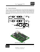
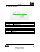
1.2 THEORY OF OPERATION
The GCU unit monitors and controls the gyroscope unit’s rotary wheel displacement about the Pitch and
Yaw axis. The GCU converts the sensed signal from the pickup coils into the appropriate torque
commands to keep the gyro wheel in the center of its travel. The output of the system is proportional to the
pitch and yaw rate inputs to the gyro. These rate values are available in both analog and digital output
formats. The GCU unit provides all of the necessary spin motor start and drive signals, torque motor drive,
pickoff excitation signals, and pickoff amplification for the gyro unit. Figure 2 shows the block diagram of
the GCU unit.
FILTER
ADC
COMP.
DAC
FILTER
ADC
COMP.
DAC
DIGITAL
FILTER
DIGITAL
FILTER
PREAMP
POWER AMP
PREAMP POWER AMP
X PICKOFF
Y PICKOFF
X TORQUE
Y TORQUE
STARTUP
USB
CTRLR
MICRO
CNTRL
FLOATING
POINT DSP
TEST EQUIPMENT
(LAPTOP)
SPIN MOTOR
DRIVER
FLASH
DDS
EXCITE
XSPIN
YSPIN
Figure 2 GCU, Block Diagram
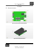
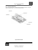
Figure 3 GCU 3-Dimensional Model