
User`s guide

Gyro Control Unit (GCU)
User’s Guide
4
MaxMetrix, Scottsdale, AZ
PN: GCU-2K1-UG:RevI.2 NGC
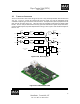
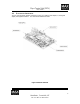
Figure 4 GCU Board Layout, Mechanical Dimensions .................................................................................. 7
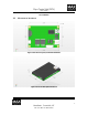
Figure 5 GCU unit with optional heat sink
..................................................................................................... 7
Figure 6 Power Supply Connector
.................................................................................................................. 8
Figure 7 Digital Output Connector
................................................................................................................. 8
Figure 8 Analog Output Connector
................................................................................................................ 8
Figure 9 Electrical Interfaces
.......................................................................................................................... 9
Figure 10 Power Supply Connector, Illustration
...........................................................................................10
Figure 11 Analog Output Connector
.............................................................................................................11
Figure 12 Digital Output Connector
..............................................................................................................12
Figure 13 Digital Output, SPI Data Format
...................................................................................................13
Figure 14 G-2000 Connector
.........................................................................................................................13
Figure 15 GCU Interface Connectors
............................................................................................................15
Figure 16 GCU Unit connected to the G-2000 gyro
......................................................................................16
Figure 17 Cal / Status Commands, Gyro Setup
.............................................................................................18
Figure 18 Oscilloscope Function, Gyro Setup
...............................................................................................21
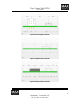
Figure 19 Spectrum Analyzer with 800Hz notch filter turn OFF
..................................................................23
Figure 20 Spectrum Analyzer with 800Hz notch filter turned ON
................................................................24
Figure 21 Open Loop Response, Bode Analyzer
..........................................................................................26
Figure 22 Bode Plot Analyzer
.......................................................................................................................27
Figure 23 Notch Filter Coefficient Adjustments
...........................................................................................29
Figure 24 Filter Coefficients
..........................................................................................................................30
Figure 25 Firmware Loader Application
.......................................................................................................31
Figure 27. Browse File Function, Graphical User Interface (GUI)
...............................................................32
Figure 28 Examples of a nicely tune system, Spectrum Plot
.........................................................................40
Figure 29 Examples of a nicely tuned system, Bode Plot
..............................................................................40
TABLES
Table 1. Available Firmware Files, Extension(s)
..........................................................................................32
Table 2 Parameter Button Usage
...................................................................................................................36
Table 3 Parameter Button Usage
...................................................................................................................36
Table 4 Mechanical Dimensions
...................................................................................................................41
Table 5 Electrical Specifications
...................................................................................................................41
Table 6 Environmental Specifications
...........................................................................................................41
WARNING!!! & CAUTION!!!
Warnings and Cautions have been boxed in to bring attention to the user to proceed with caution but, only
after making all of the appropriate checks and verifications. Failure to adhere to the information can have
catastrophic results and can end up damaging the units beyond repair.