
User`s guide

Gyro Control Unit (GCU)
User’s Guide
29
MaxMetrix, Scottsdale, AZ
PN: GCU-2K1-UG:RevI.2 NGC
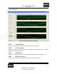
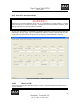
4.1.5 NOTCH FILTER ADJUSTMENTS
WARNING!!!
Adjusting the notch filter parameters should only be accomplished by a trained operator or someone
familiar with the GCU unit and the gyroscope. Changing the notch filter placements, steepness, and/or
damping coefficients can cause the system to be unstable.
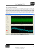
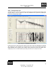
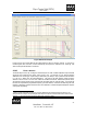
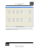
The GCU unit incorporates five independent programmable digital filters to remove spectral line and noise
components in the gyro signal. This is accomplished by utilizing a cascade of bilinear-quad IIR filters.
The bi-quads are programmed for the type of filter, the frequency, and the bandwidth, respectively.
Figure 23 Notch Filter Coefficient Adjustments
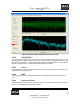
4.1.5.1 WRITE TO DSP
This command stores the filter parameters in the GCU RAM. The Filter Parameters are read at power on
and sent to the DSP.