
User`s guide

Gyro Control Unit (GCU)
User’s Guide
28
MaxMetrix, Scottsdale, AZ
PN: GCU-2K1-UG:RevI.2 NGC
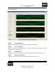
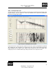
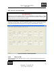
4.1.4.2 AXIS
This radio button allows the user to select either the Pitch or the Yaw axis for analysis.
4.1.4.3 TRACE COLOR
The trace color “radio buttons” allow the user to change pen colors and plot a new plot on top of an old one
for comparison.
4.1.4.4 PARAMETERS
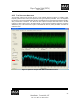
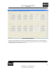
4.1.4.4.1 START FREQUENCY
5
This text box allows the user to set the desired starting frequency in Hz of the Bode analyzer.
4.1.4.4.2 STOP FREQUENCY
This text box allows the user to set the desired stopping frequency in Hz of the Bode analyzer
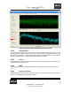
4.1.4.4.3 EXCITATION AMPLITUDE
6
The text box sets the excitation amplitude to be summed into the DAC during the Bode analysis.
4.1.4.4.4 SAMPLE RATE
This drop down list sets the sample rate of the bode process. The Fourier Integral values are calculated at
this rate. The system decimates the output by a factor to allow the bode values to be stored locally in the
GCU until the process is over at which time the data is sent to the PC over the USB interface.
4.1.4.4.5 DURATION
The duration box sets the test duration in seconds the sweep generator shall sweep from the start frequency
to the stop frequency.
4.1.4.5 START | STOP
This button starts and stops the bode analyzer.
5
The start and stop frequency values allow the user to zoom in on a region for inspection.
6
Setting the Amplitude too high will cause the gyro to be unstable. This is indicated by the crashing sound
of the wheel being forced against the hard stops of the gyro cage.