
User`s guide

Gyro Control Unit (GCU)
User’s Guide
19
MaxMetrix, Scottsdale, AZ
PN: GCU-2K1-UG:RevI.2 NGC
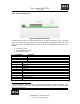
4.1.1.1.1 TORQUER ON | OFF
This command turns on and off the Torquer DAC updates. When Torquer Off is selected, the torquer
outputs are set to the middle range value of 0x8000 (i.e. No Torque Applied)
4.1.1.1.2 MOTOR ON | OFF
This command turns on and off the gyro spin motor. Executing this command will also turns off the
torquer outputs. When the motor command is used to turn on the spin motor, the user must also send a
“torquer on” command to turn back on the torquer outputs to re-establish the control loops.
4.1.1.1.3 SAVE CALIBRATION
This command stores the entire calibration coefficient field and the filter coefficient page to the GCU flash
memory; overwriting the previous values. These values are used at startup and are sent to the GCU DSP
after the DSP boot process. The PC application also writes a file with the GCU serial number as the
filename to disk of all of the parameters stored in the GCU flash, see section 4.1.7.
4.1.1.1.3.1 Path to Save Calibration Files
This text box allows the user to set the path to save and recall the calibration files on the PC.
4.1.1.1.4 SEND COMMAND BUTTON
This button sends the selected command to the GCU.
4.1.1.1.5 ADDITIONAL INFORMATION
The additional information box allows the user to save pertinent information regarding the GCU and Gyro
under test. This information will be stored in the GCU flash memory when the save calibration button is
selected.
4.1.1.1.6 READ VALUES FROM DSP
This command reads the DSP control loop coefficients and places the results in their associated text boxes.
4.1.1.1.7 WRITE VALUES TO DSP
This command updates the DSP with the values in the text boxes. The Update Command does not write
the values to flash memory; it only replaces the operational values so the user can assess their performance
before writing them to flash. Once the user is satisfied with the performance; the “Save Calibration”
command should be used to permanently store the values.
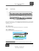
4.1.1.2 CONTROL LAW PARAMETERS
The GCU unit utilizes a proportional plus integral (PI) controller to “cage” the rotating wheel. The gyro
control loop bandwidth is related to the amount of gain each of the channels contributes to the “caging”
loop process. The control law parameters box allows the user to change the gains of the controller.
4.1.1.2.1 PROPORTIONAL GAIN, K
P
This text boxes allows the user to set the amount of proportional gain that should be used to control each of
the separate axis.