
User`s guide

Gyro Control Unit (GCU)
User’s Guide
18
MaxMetrix, Scottsdale, AZ
PN: GCU-2K1-UG:RevI.2 NGC
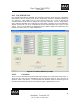
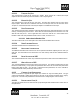
4.1.1 CAL/STATUS TAB
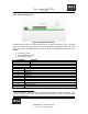
The Cal/Status tab contains the individual gyro commands to setup the control loop gains, compensation
filter frequency, the ADC and DAC offset, the ADC sample delay, and specific information regarding the
GCU module (i.e., serial number, DSP, PIC, FPGA firmware versions, etc.). Figure 14 shows the tab
command selection and text boxes for inputting the control loop coefficients. The GCU comes from the
factory with these parameters set for a particular gyro serial number. Should the GCU be associated with a
different gyroscope the unit can be re-calibrated and the associated parameters store in the GCU flash
memory. The GCU serial numbers are implemented using a hardware digital serial number device and
therefore are unique to each GCU module manufactured.
Figure 17 Cal / Status Commands, Gyro Setup
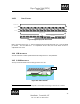
4.1.1.1 COMMANDS
The GCU can be commanded to request and status report message, turn on and off the torquer motors, on
and off the spin motor (this will automatically turns off the torquer motors as well), and store the
calibration values in flash memory. In normal operation the calibration values are read during power up
and sent to the DSP before the loops are closed each time power is applied to the GCU unit.