
User`s guide

Gyro Control Unit (GCU)
User’s Guide
16
MaxMetrix, Scottsdale, AZ
PN: GCU-2K1-UG:RevI.2 NGC
3 APPLYING POWER
WARNING!!!
The user should verify the power supplies are correctly adjusted and the power is properly connected
before applying power to the GCU unit. Failure to due so can damage the GCU unit and/or the gyroscope
beyond repair!
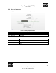
Before applying power the users should verify the appropriate voltages appear on the correct interfaces pins
of the power supply connector. After applying power, the gyroscope should immediately spin up; this is
indicated by the audible sound emitted from the spin motor located inside the gyroscope unit. The loop is
closed ~3seconds after the spin-up cycle; the analog and digital data is available in approximately 3sec after
the spin up cycle is complete.
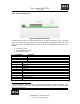
3.1 LED STATUS INDICATORS
There are four light emitting diodes (LED) to provide status to the user. There are two LEDs dedicated to
the microcontroller and two for the digital signal processor unit.
3.1.1 MICROCONTROLLER STATUS
The first LED indicates DSP program load cycle and then subsequently is used as a system heart beat
indicator. The Heartbeat is typically once per second allowing the user to visually inspect that the GCU is
functioning properly. The second LED is unassigned as a spare.
3.1.2 DSP STATUS
The green LED indicates the control loop is closed, the red LED indicates the control loop is open. The
unit is initialized to close the loop after the boot process is complete (i.e., the Green LED is ON).
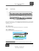
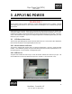
Figure 16 GCU Unit connected to the G-2000 gyro