
User`s guide

Gyro Control Unit (GCU)
User’s Guide
15
MaxMetrix, Scottsdale, AZ
PN: GCU-2K1-UG:RevI.2 NGC
2 SETUP
WARNING!!!
The GCU unit should be setup in the following order, failure to do so could result in damaging the GCU
module and or the gyroscope unit.
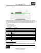
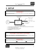
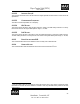
RATE
SENSOR
POWER SUPPLY
(+5Vdc, +15VDC, -15VDC, +28VDC)
ANALOG OUTPUTS
(PITCH, YAW)
DIGITAL OUTPUTS
(PITCH, YAW)
USB PERFORMANCE
ANALYZER
GYRO CONTROL UNIT
(GCU)
Figure 15 GCU Interface Connectors
1. Connect the gyroscope securely to the gyro control unit, before make any of the other connections.
2. Connect the USB connection to the PC.
3. Connect the Digital Output connector (if utilized).
4. Connect the Power Supply (power turn off).
5. Apply Power.
CAUTION!!! CAUTION!!! CAUTION!!!
DO NOT OVER TIGHTEN THE HEX MOUNTING HARDWARE at the G-2000/GCU interface.
OVER-TIGHTENING these screws will permanently damage the GCU connector.
WARNING!!!
The power connector should be mated before the power is applied (i.e., Do NOT
hot swap the connector).