
User`s guide

Gyro Control Unit (GCU)
User’s Guide
13
MaxMetrix, Scottsdale, AZ
PN: GCU-2K1-UG:RevI.2 NGC
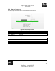
1.4.3.1 DATA FORMAT
D15
D14
D13
D12
D11
D10
D09
D08 D07
D06
D05 D04
D03
D02
D01
D00
32-BIT DATA VALUE
D15
D14
D13 D12
D11 D10
D09
D08 D07
D06 D05
D04
D03
D02
D01
D00
D31 D30
D29
D28 D27
D26 D25
D24
D23
D22
D21
D20
D19
D18
D17
D16
D15
D14 D13
D12
D11
D10
D09
D08
D07
D06 D05
D04
D03 D02
D01 D00
S LSB
LSBS
PITCH VALUE
YAW VALUE
SPI FRAME SYNC
SPI CLOCK
SPI DATA
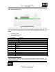
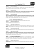
Figure 13 Digital Output, SPI Data Format
Data is valid when FSI is logic “1”. Data is sampled on the rising edge of the SPI clock. There are 32bits
per transfer. The first 16bits are a 2’s complements PITCH value; the second 16bits are the 2’s
complement YAW value.
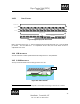
1.4.4 USB INTERFACE
The USB connector is used to upload software and configure the GCU unit parameters.
1.4.5 G-2000 INTERFACE
The Gyro Connector interfaces the G-2000 gyro to the GCU unit.
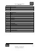
Figure 14 G-2000 Connector
2
2
Note: A 0.035” Hex-Allen wrench is required to connect/disconnect the gyro from the GCU module.
Pin 1