Gyro Control Unit (GCU) User’s Guide Gyro Control Unit (GCU) User’s Guide Revision: I.2 Northrop Grumman Date: 10/07/11 1 MaxMetrix, Scottsdale, AZ PN: GCU-2K1-UG:RevI.
Gyro Control Unit (GCU) User’s Guide CONTENTS 1 Scope..................................................................................................................................................... 5 1.1 Overview .......................................................................................................................................... 5 1.2 Theory of Operation ......................................................................................................................... 6 1.
Gyro Control Unit (GCU) User’s Guide 4.1.2.4 Number of Samples ........................................................................................................21 4.1.2.5 Start | Stop .......................................................................................................................22 4.1.2.6 Connect | Disconnect ......................................................................................................22 4.1.3 The Spectrum Analyzer .....................................
Gyro Control Unit (GCU) User’s Guide Figure 4 GCU Board Layout, Mechanical Dimensions .................................................................................. 7 Figure 5 GCU unit with optional heat sink ..................................................................................................... 7 Figure 6 Power Supply Connector.................................................................................................................. 8 Figure 7 Digital Output Connector .............
Gyro Control Unit (GCU) User’s Guide 1 SCOPE This manual describes the use and setup of the G-2000 Gyro Control Unit (GCU) product, Model No: GCU2K1. 1.1 OVERVIEW The GCU2K1 gyro control unit is designed to provide digital control for the Northrop Grumman Company, G-2000 dual rate sensor products. Figure 1 GCU2K1, Gyro Control Unit (GCU) The GCU digital control unit is based on the Texas Instrument’s TMS320VC33-150 Floating-Point Digital Signal Processing unit.
Gyro Control Unit (GCU) User’s Guide 1.2 THEORY OF OPERATION The GCU unit monitors and controls the gyroscope unit’s rotary wheel displacement about the Pitch and Yaw axis. The GCU converts the sensed signal from the pickup coils into the appropriate torque commands to keep the gyro wheel in the center of its travel. The output of the system is proportional to the pitch and yaw rate inputs to the gyro. These rate values are available in both analog and digital output formats.
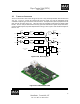
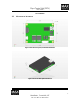
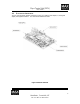
Gyro Control Unit (GCU) User’s Guide GCU Interfaces 1.3 MECHANICAL INTERFACE Figure 4 GCU Board Layout, Mechanical Dimensions Figure 5 GCU unit with optional heat sink 7 MaxMetrix, Scottsdale, AZ PN: GCU-2K1-UG:RevI.
Gyro Control Unit (GCU) User’s Guide Figure 6 Power Supply Connector Figure 7 Digital Output Connector Figure 8 Analog Output Connector 8 MaxMetrix, Scottsdale, AZ PN: GCU-2K1-UG:RevI.
Gyro Control Unit (GCU) User’s Guide 1.4 ELECTRICAL INTERFACES The GCU unit has several interface connectors for power, gyro interface, rate outputs (i.e., analog and digital), test equipment interface. The connectors are defined as follows: Figure 9 Electrical Interfaces 9 MaxMetrix, Scottsdale, AZ PN: GCU-2K1-UG:RevI.
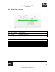
Gyro Control Unit (GCU) User’s Guide 1.4.1 POWER SUPPLY INTERFACE Figure 10 Power Supply Connector, Illustration Part Number DF1B – 6DP – 2.5DS(01) DF1B – 6DS – 2.5RC DF1B – 2022SCA DF1B – 2428SCA Pin Number 1 2 3 4 5 6 Description Board Connector Mating Connector CRIMP PIN 20 – 22AGW CRIMP PIN 24 – 28AGW Description +5Vdc GROUND +12Vdc to 18Vdc +28Vdc -12Vdc to 18Vdc GROUND 10 MaxMetrix, Scottsdale, AZ PN: GCU-2K1-UG:RevI.
Gyro Control Unit (GCU) User’s Guide 1.4.2 ANALOG INTERFACE The analog outputs are scaled ±10V for an associated rate input of ±200°/sec. Figure 11 Analog Output Connector Part Number DF13 – 4P – 1.25H(50) DF13 – 4S – 1.25C DF13 – 2630SCFA Pin Number 1 2 3 4 Description Board Connector Mating Connector CRIMP PIN Description YAW NO CONNECTION SIGNAL GROUND PITCH 11 MaxMetrix, Scottsdale, AZ PN: GCU-2K1-UG:RevI.
Gyro Control Unit (GCU) User’s Guide 1.4.3 DIGITAL INTERFACE Figure 12 Digital Output Connector The digital format consists of two 16bit signed values, one for pitch, and the other for yaw. The digital values are sent as a single 32-bit digital word using the high speed serial peripheral interface (SPI) of the TMS320VC33 DSP. The digital interface conforms to the low voltage differential signaling (LVDS 1) standard. • • • Clock Rate: 7.5 Mhz Word Output Rate: 21.6Khz Bit Width: 133.
Gyro Control Unit (GCU) User’s Guide 1.4.3.
Gyro Control Unit (GCU) User’s Guide Part Number STM025L2HN STL025L2HN 4-1589483-5 1-1589483-7 Pin Number 1 2 3 4 5 6 7 8 9 10 11 12 13 14 15 16 17 18 19 20 21 22 23 24 25 Description Nanonics PN (Metal) Nanonics PN (Plastic) Tyco PN(Metal) Tyco PN(Plastic) Description SPIN MOTOR A HI SPIN MOTOR A LO +15Vdc GROUND EXCITATION HI EXCITATION LO Y TORQUE LO Y TORQUE HI X TORQUE LO X TORQUE HI X PICKOFF Y PICKOFF SPIN MOTOR B HI SPIN MOTOR B LO CASE GROUND -15Vdc NO CONNECTION (NC) NO CONNECTION (NC) NO CONNE
Gyro Control Unit (GCU) User’s Guide 2 SETUP WARNING!!! The GCU unit should be setup in the following order, failure to do so could result in damaging the GCU module and or the gyroscope unit. DIGITAL OUTPUTS (PITCH, YAW) ANALOG OUTPUTS (PITCH, YAW) RATE SENSOR POWER SUPPLY (+5Vdc, +15VDC, -15VDC, +28VDC) GYRO CONTROL UNIT (GCU) USB PERFORMANCE ANALYZER Figure 15 GCU Interface Connectors 1. 2. 3. 4. 5. Connect the gyroscope securely to the gyro control unit, before make any of the other connections.
Gyro Control Unit (GCU) User’s Guide 3 APPLYING POWER WARNING!!! The user should verify the power supplies are correctly adjusted and the power is properly connected before applying power to the GCU unit. Failure to due so can damage the GCU unit and/or the gyroscope beyond repair! Before applying power the users should verify the appropriate voltages appear on the correct interfaces pins of the power supply connector.
Gyro Control Unit (GCU) User’s Guide 4 PERFORMANCE ANALYZER A Microsoft Windows compatible software application provides the user the ability to observe the G-2000 performance, as well as, adjust and store several of the key tuning parameters in the GCU FLASH memory. Operating System Requirement: • Windows Compatible Processing Platform running Windows XP or equivalent. 4.
Gyro Control Unit (GCU) User’s Guide 4.1.1 CAL/STATUS TAB The Cal/Status tab contains the individual gyro commands to setup the control loop gains, compensation filter frequency, the ADC and DAC offset, the ADC sample delay, and specific information regarding the GCU module (i.e., serial number, DSP, PIC, FPGA firmware versions, etc.). Figure 14 shows the tab command selection and text boxes for inputting the control loop coefficients.
Gyro Control Unit (GCU) User’s Guide 4.1.1.1.1 TORQUER ON | OFF This command turns on and off the Torquer DAC updates. When Torquer Off is selected, the torquer outputs are set to the middle range value of 0x8000 (i.e. No Torque Applied) 4.1.1.1.2 MOTOR ON | OFF This command turns on and off the gyro spin motor. Executing this command will also turns off the torquer outputs.
Gyro Control Unit (GCU) User’s Guide 4.1.1.2.2 INTEGRAL GAIN, KI This text boxes allows the user to set the amount of integral gain that should be used to control each of the separate axis. 4.1.1.2.3 COMPENSATOR FREQUENCY This text box set the compensator cut-in frequency. 4.1.1.2.4 ADC OFFSET This text box allows the user to trim out the Pickoff ADC offsets. The ideal setting would be 0 or exactly the mid-scale value for the signed 16bit dynamic range (+/- 32,768). 4.1.1.2.
Gyro Control Unit (GCU) User’s Guide 4.1.2 THE SCOPE Figure 18 Oscilloscope Function, Gyro Setup 4.1.2.1 CHANNEL ENABLE This check box allows the user to select the particular channel(s) to be displayed. 4.1.2.2 AUTO Y RANGING This check box turns on and off the auto-range Y coordinate. When deselected the range is continually adapted to accept the largest value read. 4.1.2.3 SAMPLE RATE This drop down selection box allows the user to select a different sample rate for each sample record. 4.1.
Gyro Control Unit (GCU) User’s Guide 4.1.2.5 START | STOP The Stop/Start command starts and stops the oscilloscope traces. 4.1.2.6 CONNECT | DISCONNECT The connect/disconnect command establishes the communication link with the USB port on the PC. Indication of the status of the communications link is given in the label fields located at the lower left-hand corner of the GCU Setup application. 22 MaxMetrix, Scottsdale, AZ PN: GCU-2K1-UG:RevI.
Gyro Control Unit (GCU) User’s Guide 4.1.3 THE SPECTRUM ANALYZER The Spectrum Analyzer tab provides the user a full featured Spectrum Analyzer to evaluate system frequency peaks and noise in the power spectrum of the gyroscope being evaluated. This is accomplished by collecting a one second sample buffer and then calculating the power spectral density estimation (PSDE) using a Fast Fourier Transform.
Gyro Control Unit (GCU) User’s Guide Figure 20 Spectrum Analyzer with 800Hz notch filter turned ON 4.1.3.1 DATA SELECT The Data Select radio buttons allow the user to select the input source to the Spectrum Analyzer. The spectrum analyzer first applies a window function (i.e., Hanning Window) to the input data stream and then calculates a 32768 point FFT.
Gyro Control Unit (GCU) User’s Guide 4.1.3.5 FREQUENCY RANGE The frequency range drop down menu selects the frequency span from zero to the selected end frequency. 4.1.3.6 START | STOP This button starts and stops the Spectrum Analyzer function. 25 MaxMetrix, Scottsdale, AZ PN: GCU-2K1-UG:RevI.
Gyro Control Unit (GCU) User’s Guide 4.1.4 THE BODE ANALYZER The Bode Plot Analyzer allows the user the ability to observe the gyro performance under different control loop gain settings. The servo response or control loop bandwidth can be optimized by adjusting the proportional and integral gain settings. Figure 21 Open Loop Response, Bode Analyzer Figure 18 trace shows a typical open-loop response of the control system.
Gyro Control Unit (GCU) User’s Guide Figure 22 Bode Plot Analyzer Figure 19 shows the several different gain setting and their effect on the Pitch channel. As the gain in increased (green, blue, red, black, increase respectively) the response in extended out to ~250Hz @ -3db where it intercepts the 266.667Hz notch filter. 4.1.4.
Gyro Control Unit (GCU) User’s Guide 4.1.4.2 AXIS This radio button allows the user to select either the Pitch or the Yaw axis for analysis. 4.1.4.3 TRACE COLOR The trace color “radio buttons” allow the user to change pen colors and plot a new plot on top of an old one for comparison. 4.1.4.4 PARAMETERS 4.1.4.4.1 START FREQUENCY 5 This text box allows the user to set the desired starting frequency in Hz of the Bode analyzer. 4.1.4.4.
Gyro Control Unit (GCU) User’s Guide 4.1.5 NOTCH FILTER ADJUSTMENTS WARNING!!! Adjusting the notch filter parameters should only be accomplished by a trained operator or someone familiar with the GCU unit and the gyroscope. Changing the notch filter placements, steepness, and/or damping coefficients can cause the system to be unstable. The GCU unit incorporates five independent programmable digital filters to remove spectral line and noise components in the gyro signal.
Gyro Control Unit (GCU) User’s Guide Figure 24 Filter Coefficients Figure 21, shows the digital filter coefficients calculated from the filter selection tab. These coefficients are downloaded to the GCU and used in calculating the bi-quad filter responses. They are not editable and are simply presented as information for the user. 30 MaxMetrix, Scottsdale, AZ PN: GCU-2K1-UG:RevI.
Gyro Control Unit (GCU) User’s Guide 4.1.6 FIRMWARE LOADER The firmware for the microcontroller and digital signal processor are completely downloadable using a standard windows laptop using a USB interface. The USB interface is connected with the standard USB cable P/N, descriptor… The USB drivers are included on the distribution disk or downloadable from the MaxMetrix website (i.e. www.maxmetrix.com). Figure 25 Firmware Loader Application 4.1.6.
Gyro Control Unit (GCU) User’s Guide Figure 26. Browse File Function, Graphical User Interface (GUI) The File of type selector allows the user to filter for the desired extension. The available extensions are as follows: Extension .hex .m0 Table 1. Available Firmware Files, Extension(s) 4.1.6.2 Description Microcontroller Firmware DSP Firmware LOAD The LOAD command button downloads starts the download of the selected file. Progress of the download is displayed as a percentage from 0-100%.
Gyro Control Unit (GCU) User’s Guide 4.1.6.3 NO-OP The NO-OP (no operation) command button tests the communications link with the microcontroller on the GCU. If the link is valid a message is displayed indicating the link PASSED. If the application is unable to establish communications with the GCU unit the message displays FAILED. 4.1.6.4 DSP ENTRY POINT The DSP Entry Point Text Box sets the starting address for the DSP Code. “AUTO” automatically finds the address in the object code file.
Gyro Control Unit (GCU) User’s Guide 4.1.7 MANUFACTURING REPORT The software automatically generates a text file with all of the associated information regarding the parameters and setup of the GCU unit. Additional information regarding the “Born on Date” (i.e., the date the GCU was created), the associated Gyroscope Serial Number, the last date and time the GCU was configured, etc. is contained in this report. All of the information is stored in the Flash Memory located on the GCU unit.
Gyro Control Unit (GCU) User’s Guide Pitch_F4_c2=0.98399554879006 Pitch_F4_c3=0.99199777439503 Pitch_F4_c4=-1.93051669200337 Pitch_F4_c5=0.99199777439503 Pitch_F5_c1=-1.97849669083323 Pitch_F5_c2=0.99196564994852 Pitch_F5_c3=0.99598282497426 Pitch_F5_c4=-1.97849669083323 Pitch_F5_c5=0.99598282497426 Pitch_F6_c1=-1.91665852069855 Pitch_F6_c2=0.919996082782745 Pitch_F6_c3=0.000834393780678511 Pitch_F6_c4=0.00166878756135702 Pitch_F6_c5=0.000834393780678511 Yaw_F1_c1=-1.94634687900543 Yaw_F1_c2=0.
Gyro Control Unit (GCU) User’s Guide 4.2 PARAMETER BUTTONS AND STORAGE Table 2 Parameter Button Usage Button Read Calibration Set Defaults Read Gyro Contents Save Calibration Write to DSP Read From DSP Description Reads the calibration file named with the filename associated with the serial number (i.e., G-0000-0000-0000.dat) from of the associated GCU. Note: the zeros in the example will actually be the unique serial number reported back from the specific GCU module.
Gyro Control Unit (GCU) User’s Guide 5 SOFTWARE LICENSE COPYRIGHT 2008, by MaxMetrix, LLC. This Manual, the software program, and related documentation contain proprietary and confidential information of MaxMetrix, LLC. including but not limited to Algorithms, Processes, Procedures, and Methods. The Manual and all information contained herein, the Program, and Documentation are and shall remain the exclusive property of MaxMetrix, LLC.
Gyro Control Unit (GCU) User’s Guide publication of the program in the operating characteristics of the computer hardware, test instruments, or operating systems, nor for problems in the interaction of the program with non- MaxMetrix, LLC. software components. LIMITATION of REMEDIES MaxMetrix, LLC.’ entire liability and your exclusive remedy shall be refund of the purchase price, regardless of any defect in the program or negligence of MaxMetrix, LLC. and regardless of the claim or form of action.
Gyro Control Unit (GCU) User’s Guide 6 FAQ AND TECHNICAL SUPPORT The section presents some of the possible remedies to different issues that may occur while exercising the unit with the gyro setup application. 6.1 GYRO SETUP SOFTWARE DOES NOT RESPOND TO COMMANDS • • Try to disconnect and then reconnect the USB service using the CONNECT button in the Gyro Setup application. Try to reboot the Windows PC, then restarting the Gyro Setup application G-2000 GYRO IS UNSTABLE AFTER POWER IS APPLIED 8 6.
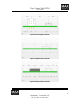
Gyro Control Unit (GCU) User’s Guide Figure 27 Examples of a nicely tune system, Spectrum Plot Figure 28 Examples of a nicely tuned system, Bode Plot 40 MaxMetrix, Scottsdale, AZ PN: GCU-2K1-UG:RevI.
Gyro Control Unit (GCU) User’s Guide GCU2K1 Specifications 6.4 MECHANICAL DIMENSIONS Description Dimension 63.5 x 43.2 x 7.62mm (2.5” x 1.7” x 0.3”) 94 grams (3.2 ounces) #2 SAE hardware Table 4 Mechanical Dimensions Width Weight Mounting Holes 6.5 ELECTRICAL SPECIFICATIONS Description Specification Voltage(s) +28Vdc 9 or +5V +/-15V Current(s) 240ma (idle) to 500ma (max. rate) Gyro Control Loop Bandwidth 200hz (typical) Maximum Rate Response 150deg/sec Table 5 Electrical Specifications 6.