
Operators Manual Instruction Manual
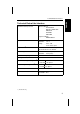
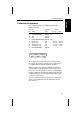
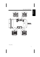

Connector Assignment
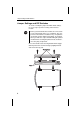
The combined interface is equipped with a 25 pin
DB25S connector.
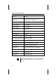
Connector Transmiss. Printer
No. Signal Type passive active
1 CHASSIS GROUND RS232C / TTY
2 TxD RS232C
3 RxD RS232C
7 SIGNAL GROUND (GND) RS232C / TTY
9 Receive Loop TTY –R-Loop +R-Loop
10 Receive Loop TTY +R-Loop –R-Loop
18 Transmission Loop TTY –T-Loop +T-Loop
21 Transmission Loop TTY +T-Loop –T-Loop
25 RDY (READY/BUSY) RS232C
The polarity of the receive and send loop alters when
the supply side changes (active/passive) ,,Printer Passi-
ve“ signifies that S1 and S2 must be in position 1.
When using the serial interface RS232C, the interface
cable must be checked for proper contact connections.
In the case of software printer control (e.g. XON/XOFF)
the pin assignment is identical for both the standard and
combined interface. The hardware printer control requi-
res different connections.
The pin assignment of the TTY part of the combined in-
terface corresponds to the pin assignment of the old
TTY interface.
13
1
25
14
ENGLISHENGLISHFRANÇAISITALIANOESPAÑOL
Connector Assignment
5