® A PRODUCT FROM TALLYGENICOM Operator’s Manual Bedienungsanleitung Manuel d’utilisation Istruzioni per l’operatore Instrucciones para el uso RS232C/TTY Interface Module RS232C/TTY-Schnittstellenmodul Module d’interface RS232C/TTY Modulo interfaccia RS232C/TTY Modulo de interfaz RS232C/TTY
This device fulfils the European standards requirements by complying with the Directive of the Commission dated May 3, 1989 (89/336/EEC) relating to electro-magnetic compatibility and the Directive dated February 19, 1973 (73/23/EEC) relating to low-voltage electrical equipment. Conformity with the above mentioned Directives is indicated by the CE symbol attached to the device.
ENGLISH RS232C/TTY Interface Module ESPAÑOL ITALIANO FRANÇAIS ENGLISH Operator’s Manual
Contents of the Package Contents of the Package Together with the interface module you receive this operator’s manual. If the interface module is damaged inform your dealer. Working with the Printer The operator’s manual of the printer gives you detailed information about how to operate the printer (inserting paper, inserting/replacing ribbon cassette, programming via the control panel etc.). Interface function test (hex-dump), see printer operator’s manual.
Technical Data of the Interface Word feedback: X-ON/X-OFF Robust X-ON/X-OFF ENQ/STX ETX/ACK ACK/NAK ENGLISH Signal feedback: READY/BUSY Data format Stop bit(s): 1 or 2 Data bits: 7 or 8 Parity: none, odd, even, mark, space Signal level1) Transmission and receive loop have a rated current level of +20 mA. Cable length TTY/20 mA: 1000 m (max.) RS232C: 15 m (max.
Interface Description Interface Description Two different serial interfaces are located on this component: – RS232C and – TTY 20mA. Different to the standard RS232C interface not all signals are available. Whereas the RS232C interface requires one line for the send and receive line respectively, the TTY interface requires twice as many lines. Here one current loop for the receive data (Receive Loop (RxLoop)) and one current loop for transmission data (Transmit Loop (TxLoop)) are formed.
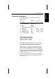
Connector Assignment ENGLISH Connector Assignment The combined interface is equipped with a 25 pin DB25S connector. Transmiss. Type 1 2 3 7 9 10 18 21 25 RS232C / TTY RS232C RS232C RS232C / TTY TTY TTY TTY TTY RS232C CHASSIS GROUND TxD RxD SIGNAL GROUND (GND) Receive Loop Receive Loop Transmission Loop Transmission Loop RDY (READY/BUSY) 25 –R-Loop +R-Loop –T-Loop +T-Loop +R-Loop –R-Loop +T-Loop –T-Loop 1 FRANÇAIS 13 Printer passive active ENGLISH Connector No.
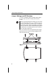
Jumper Settings and DIP Switches Jumper Settings and DIP Switches To check or modify the jumper and DIP switch settings, it is necessary to open the housing of the interface module. STOP Before you touch the interface module, be sure to touch a non-coated metal surface (e.g. a radiator). The components of the interface module are very susceptible to electrostatic charges which may build up, for example, when you walk on a carpet.
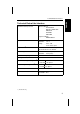
S1* S2* 2 S1 X2 1 ENGLISH 1 S2 B5 X12 S4 S3* S4* 1 2 3 4 1 2 3 4 OFF OFF ITALIANO S3 Computer connection FRANÇAIS X1 ESPAÑOL 2 ENGLISH Jumper Settings and DIP Switches * factory setting 7
Jumper Settings and DIP Switches Jumper Function B5 open* B5 closed no connection GND and chassis GND and chassis connected Slide switches Function S1 in position 1 T-Loop passive S2 in position 1 R-Loop passive S1 in position 2* T-Loop active S2 in position 2* R-Loop active DIP switches Function S3.1 closed / S3.2 open level position RDY S3.1 open / S3.2 closed* level position RDY\ S3.3 open / S3.4 closed connects RDY or RDY\ with Pin 2 or T-Loop S3.3 closed / S3.
ENGLISH RS232C/TTY-Schnittstellenmodul ESPAÑOL ITALIANO FRANÇAIS DEUTSCH Bedienungsanleitung
Lieferumfang Lieferumfang Das Schnittstellenmodul erhalten Sie zusammen mit dieser Bedienungsanleitung. Sollte das Schnittstellenmodul beschädigt sein, benachrichtigen Sie bitte Ihren Händler. Arbeiten mit dem Drucker Eine ausführliche Beschreibung zur Handhabung des Druckers (Papier einlegen, Farbbandkassette einsetzen/auswechseln, Programmieren über das Bedienfeld usw.) wird in der Bedienungsanleitung des Druckers gegeben.
Technische Daten der Schnittstelle Übertragungsprotokoll ENGLISH Technische Daten der Schnittstelle Wortrückmeldung: X-ON/X-OFF Robust X-ON/X-OFF ENQ/STX ETX/ACK ACK/NAK Stopbits: Datenbits: Parität: Signalpegel1) Sowohl Sender- als auch Empfängerschleife haben einen Nennstrompegel von +20 mA.
Schnittstellenbeschreibung Schnittstellenbeschreibung Auf dieser Baugruppe sind zwei verschiedene serielle Schnittstellen untergebracht: – RS232C und – TTY 20mA. Gegenüber der Standardschnittstelle RS232C sind hier allerdings nicht alle Signale verfügbar. Während bei der RS232C-Schnittstelle für die Sendeleitung und für die Empfangsleitung jeweils eine Leitung benötigt wird, sind bei der TTY-Schnittstelle dafür doppelt so viele Leitungen erforderlich.
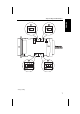
Buchsenbelegung ENGLISH Buchsenbelegung Die Kombi-Schnittstelle ist mit einer 25-poligen DB25SBuchse ausgestattet. Übertragungsart 1 2 3 7 9 10 18 21 25 RS232C/TTY RS232C RS232C RS232C/TTY TTY TTY TTY TTY RS232C CHASSIS GROUND TxD RxD SIGNAL GROUND (GND) Empfangsschleife Empfangsschleife Sendeschleife Sendeschleife RDY (READY/BUSY) 25 –R-Loop +R-Loop –T-Loop +T-Loop +R-Loop –R-Loop +T-Loop –T-Loop 1 FRANÇAIS 13 Drucker passiv aktiv DEUTSCH AnschlußNr.
Brückeneinstellungen und DIP-Schalter Brückeneinstellungen und DIP-Schalter Um die Brückeneinstellungen und DIP-Schalter zu überprüfen bzw. zu verändern, müssen Sie das Gehäuse des Schnittstellenmoduls öffnen. STOP Bevor Sie das Schnittstellenmodul anfassen, sollten Sie eine unbeschichtete Metallfläche (z.B. einen Heizkörper) berühren. Die Komponenten auf der Schnittstelle sind gegen statische Elektrizität, die Sie z.B. beim Gehen auf einem Teppich aufbauen können, sehr empfindlich.
S1* S2* 2 S1 X2 1 DEUTSCH 1 S2 B5 X12 S4 S3* S4* 1 2 3 4 1 2 3 4 OFF OFF ITALIANO S3 RechnerRechneranschluß FRANÇAIS X1 ESPAÑOL 2 ENGLISH Brückeneinstellungen und DIP-Schalter * werksseitige Voreinstellung 7
Brückeneinstellungen und DIP-Schalter Brücke Funktion B5 offen* B5 zu keine Verbindung GND und Chassis GND und Chassis verbunden Schiebeschalter Funktion S1 in Position 1 T-Loop passiv S2 in Position 1 R-Loop passiv S1 in Position 2* T-Loop aktiv S2 in Position 2* R-Loop aktiv DIP-Schalter Funktion S3.1 zu / S3.2 offen Pegellage RDY S3.1 offen / S3.2 zu* Pegellage RDY\ S3.3 offen / S3.4 zu verbindet RDY oder RDY\ mit Pin 2 oder T-Loop S3.3 zu / S3.
ENGLISH Module d’interface RS232C/TTY ESPAÑOL ITALIANO FRANÇAIS DEUTSCH Manuel d’utilisation
Livraison Livraison Le module d’interface code barres est accompagné du manuel d’utilisation. Si le module d’interface était endommagé, adressez-vous directement à votre vendeur. Travaux avec l’imprimante Le manuel d’utilisation contient une description détaillée du maniement de l’imprimante (chargement du papier, placer/changer la cassette ruban, programmation par le panneau de commande, ect.). Pour la fonction test d’interface (Hex-Dump), référezvous au manuel d’utilisation.
Spécifications de l’interface Protocole de transmission ENGLISH Spécifications de l’interface Accusé de réception à mots:: X-ON/X-OFF Robust X-ON/X-OFF ENQ/STX ETX/ACK ACK/NAK DEUTSCH Rétrosignal: Format des données Bits d’arrêt: 1 ou 2 Bits de données: 7 ou 8 Parité: aucune, pair, impair, mark, space Niveau des signaux1) Boucle émettrice et boucle réceptrice ont un niveau de courant de +20 mA.
Description des interfaces Description des interfaces Cet assemblage comporte deux interfaces série différrentes: – RS232C et – TTY 20mA. A l’encontre de l’interface standard RS232C, ici tous les signaux ne sont pas disponibles. Tandis que dans l’interface RS232C, l’émission et la réception ont besoin chacune d’une ligne, l’interface TTY, elle, en aura besoin de deux fois plus.
Brochage du connecteur ENGLISH Brochage du connecteur L’interface combinée est équipée d’une fiche DB25S à 25 broches. RS232C/TTY RS232C RS232C RS232C/TTY TTY TTY TTY TTY RS232C CHASSIS GROUND TxD RxD SIGNAL GROUND (GND) Boucle de réception Boucle de réception Boucle d’émission Boucle d’émission RDY (READY/BUSY) 13 25 –R-Loop +R-Loop –T-Loop +T-Loop +R-Loop –R-Loop +T-Loop –T-Loop DEUTSCH 1 2 3 7 9 10 18 21 25 Imprimante passif actif FRANÇAIS Type de transmiss.
Réglages des passerelles et interrupteurs DIP Réglages des passerelles et interrupteurs DIP Pour contrôler ou modifier les réglages de pontage des commutateurs DIP, vous devez ouvrir le boîtier du module d’interface. STOP Avant de toucher le module d’interface, il convient de toucher une surface métallique sans revêtement (p. ex. un radiateur). Les composants de l’interface sont très sensibles à l’électricité statique que vous pouvez générer p. ex. en vous déplaçant sur un tapis.
S1* S2* 2 S1 X2 1 DEUTSCH 1 S2 B5 X12 X1 S3 Connexion à l’ordinateur FRANÇAIS 2 ENGLISH Réglages des passerelles et interrupteurs DIP S4 S4* 1 2 3 4 1 2 3 4 OFF OFF ESPAÑOL ITALIANO S3* * Préréglage d’usine 7
Réglages des passerelles et interrupteurs DIP Passarelles Fonction B5 ouvert* B5 fermé pas de liaison entre GND et châssis GND et châssis reliés Commutateurs poussoir Fonction S1 sur position 1 T-Loop passif S2 sur position 1 R-Loop passif S1 sur position 2* T-Loop actif S2 sur position 2* R-Loop actif Commutateurs DIP Fonction S3.1 fermé / S3.2 ouvert niveau: RDY S3.1 ouvert / S3.2 fermé* niveau: RDY\ S3.3 ouvert / S3.4 fermé relie RDY ou RDY\ avec broche 2 ou T-Loop S3.3 fermé / S3.
ENGLISH Modulo interfaccia RS232C/TTY ESPAÑOL ITALIANO FRANÇAIS DEUTSCH Istruzioni per l’operatore
Che cosa fa parte della consegna Che cosa fa parte della consegna Insieme al modulo interfaccia Vi vengono consegnate anche le presenti Istruzioni per l’operatore. Nel caso in cui il modulo interfaccia dovesse risultare danneggiato, Vi preghiamo di rivolgerVi al Vostro concessionario.
Dati tecnici dell’interfaccia Protocollo di trasmissione ENGLISH Dati tecnici dell’interfaccia Conferma parola: X-ON/X-OFF Robust X-ON/X ENQ/STX ETX/ACK ACK/NAK bits stops: 1 o 2 bits di dati: 7 o 8 parità: nessuna, pari, dispari, mark, space Livello dei segnali1) Sia il loop di trasmissione che il loop di ricezione hanno un livello corrente di +20 mA.
Descrizione delle interfaccia Descrizione delle interfaccia Questo modulo contiene due interfacce seriali diversi: – RS232C e – TTY 20mA. Contrariamente all’interfaccia RS232C standard, peró, non sono disponibili tutti i segnali. Mentre per l’interfaccia RS232C sono necessarie una linea di trasmissione e una linea di ricezione, l’interfaccia TTY richiede una quantità doppia di linee.
Assegnazione della boccole L’interfaccia combinata è dotata di una boccola DB25Sa 25 poli. tipo di trasmissione 1 2 3 7 9 10 18 21 25 RS232C / TTY RS232C RS232C RS232C / TTY TTY TTY TTY TTY RS232C CHASSIS GROUND TxD RxD SIGNAL GROUND (GND) loop di ricezione loop di ricezione loop di trasmissione loop di trasmissione RDY (READY/BUSY) 25 –R-Loop +R-Loop –T-Loop +T-Loop +R-Loop –R-Loop +T-Loop –T-Loop 1 FRANÇAIS 13 stampante passivo attivo DEUTSCH Assegnazioneno.
Impostazioni dei ponticelli ed interruttori DIP Impostazioni dei ponticelli ed interruttori DIP Per controllare o modificare le impostazioni dei ponticelli e dei DIP-switch, aprire la custodia del modulo interfaccia. STOP Prima di toccare il modulo interfaccia, toccare una superficie metallica (ad esempio un calorifero). I componenti dell’interfaccia sono molto sensibili all’elettricità statica che si può accumulare, per esempio, camminando su un tappeto.
S1* S2* 2 S1 X2 1 DEUTSCH 1 S2 B5 X12 S4 S3* S4* 1 2 3 4 1 2 3 4 OFF OFF ITALIANO S3 PC FRANÇAIS X1 ESPAÑOL 2 ENGLISH Impostazioni dei ponticelli ed interruttori DIP * impostazione del produttore 7
Impostazioni dei ponticelli ed interruttori DIP Ponticello Funzione B5 aperto* B5 chiuso nessun collegamento GND/Chassis GND/Chassis collegati Interruttore a scorrimento Funzione S1 in Posizione 1 T-Loop passivo S2 in Posizione 1 R-Loop passivo S1 in Posizione 2* T-Loop attivo S2 in Posizione 2* R-Loop attivo Interruttore DIP Funzione S3.1 chiuso / S3.2 aperto posizione del livello RDY S3.1 aperto / S3.2 chiuso* posizione del livello RDY\ S3.3 aperto / S3.
ENGLISH Módulo interfaz RS232C/TTY ESPAÑOL ITALIANO FRANÇAIS ESPANOL Instrucciones para el uso
Cantidad de entrega Cantidad de entrega Recibe el módulo de interfaz junto con estas instrucciones para el uso. Si el módulo de interfaz estuviese dañado, por favor, informe a su distribuidor. Trabajar con la impresora En la instrucción para el uso de la impresora encontrará una descripción detallada para el mantamiento de la impresora (inserción del papel, colocar/descambiar el cartucho de la cinta de la máquina, programar a traves del panel de funcionamiento etc.).
Especificaciónes del interfaz Protocolo de transferencia ENGLISH Especificaciónes del interfaz Acuse de recibo de palabra: X-ON/X-OFF Robust X-ON/X-OFF ENQ/STX ETX/ACK ACK/NAK Stopbit: 1o2 Bits de datos: 7 o 8 Paridad: no, par, sin paridad mark, space Nivel de señal1) Tanto el lazo del transmisión como el lazo del recepción tienen un nivel de corriente de +20 mA.
Descripción del interfaz Descripción del interfaz Este subgrupo de piezas sueltas contiene dos interfaces seriales distinos: – RS232C y – TTY 20mA. Al contrario del interfaz serial estandar RS232C, aqui no son disponibles todas las señales. Para el interfaz RS232C se necesita una línea propria para la línea de salida y la línea de recepción. Para el interfaz TTY se necesitan el doble de líneas.
Disposición del manguito ENGLISH Disposición del manguito El interfaz de combinación está equipado con un manguito DB25S de 25 alfileres. Tipo de transmisión 1 2 3 7 9 10 18 21 25 RS232C/TTY RS232C RS232C RS232C/TTY TTY TTY TTY TTY RS232C CHASSIS GROUND TxD RxD SIGNAL GROUND (GND) lazo de recepciòn lazo de recepciòn lazo de transmisiòn lazo de transmisiòn RDY (READY) 25 –R-Loop +R-Loop –T-Loop +T-Loop +R-Loop –R-Loop +T-Loop –T-Loop 1 FRANÇAIS 13 Impresora pasiva áctiva ESPANOL No.
Disposiciones de puentes y conmutadores DIP Disposiciones de puentes y conmutadores DIP Para comprobar o modificar los ajustes de los puentes y conmutadores DIP, precisa abrir la caja del módulo interfaz. STOP Antes de tocar el módulo interfaz, cuide que toca una superficie metálica no recubierta (por ejemplo, un radiador de calefacción). Los componentes del módulo interfaz están muy susceptibles a cargas electroestáticas, las cuales pueden formarse, por ejemplo, al andar sobre una alfombra.
S1* S2* 2 S1 X2 1 ESPANOL 1 S2 B5 X12 X1 S3 Conexión al ordenador FRANÇAIS 2 ENGLISH Disposiciones de puentes y conmutadores DIP S4 S4* 1 2 3 4 1 2 3 4 OFF OFF ESPAÑOL ITALIANO S3* * ajuste de la fábrica 7
Disposiciones de puentes y conmutadores DIP Puente Función B5 abierto* B5 cerrado ninguna conexión entre GND y chasis GND y chasis conectada Conmutador corredizo Función S1 en posición 1 T-Loop pasiva S2 en posición 1 R-Loop pasiva S1 en posición 2* T-Loop activa S2 en posición 2* R-Loop activa Conmutador DIP Función S3.1 cerrado / S3.2 abierto Nivel RDY S3.1 abierto / S3.2 cerrado* Nivel RDY\ S3.3 abierto / S3.4 cerrado conecta RDY o RDY\ con Pin 2 o T-Loop S3.3 cerrado / S3.
“All rights reserved. Translations, reprinting or copying by any means of this manual complete or in part or in any different form requires our explicit approval. We reserves the right to make changes to this manual without notice. All care has been taken to ensure accuracy of information contained in this manual. However, we cannot accept responsibility for any errors or damages resulting from errors or inaccuracies of information herein.” ,,Alle Rechte vorbehalten.
TALLY REPRESENTATIVES GERMANY Tally Computerdrucker GmbH Postfach 2969 D-89019 Ulm Deutschland Tel.: +49 7308 80 0 Fax: +49 7308 5903 http://www.Tally.de CANADA Tally Corp. 125 Traders Boulevard, 9 Missisauga, Ontario L4Z 2E5 Canada Phone: +1 905 8904646 Fax: +1 905 8904567 http://www.Tally.com ITALY Tally S.R.L. Via Borsini 6 I-20094 Corsico (MI) Italia Tel.: +39 02 48608 1 Fax: +39 02 48601 141 Mailbox: +39 02 48608 323 http://www.Tally.it FRANCE Tally S.A.