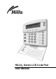
HILLS® Series LCD Code Pad User Manual
THIS MANUAL IS FURNISHED TO HELP YOU UNDERSTAND YOUR SECURITY SYSTEM AND BECOME PROFICIENT IN ITS OPERATION. ALL USERS OF YOUR SECURITY SYSTEM SHOULD READ AND FOLLOW THE INSTRUCTIONS AND PRECAUTIONS IN THIS BOOKLET BEFORE OPERATING YOUR SECURITY CONTROL SYSTEM. FAILURE TO DO SO COULD RESULT IN THE SECURITY SYSTEM NOT WORKING PROPERLY. THIS BOOKLET SHOULD BE KEPT IN AN ACCESSIBLE LOCATION FOR THE LIFE OF THE SECURITY SYSTEM.
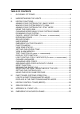
TABLE OF CONTENTS I. GLOSSARY OF TERMS .........................................................................3 II. UNDERSTANDING THE LIGHTS ...........................................................4 III. V. KEYPAD FUNCTIONS ............................................................................5 ARMING YOUR SYSTEM IN THE “AWAY” MODE.................................5 MAKING YOUR SYSTEM READY TO ARM ...........................................5 ARMING YOUR SYSTEM IN THE “STAY” MODE ............
2 Hills LCD Keypad
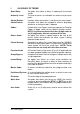
I. GLOSSARY OF TERMS Abort Delay: An option that allows a delay in reporting to the central station. Authority Level: The level of access an individual has when using an alarm panel. Central Station: Location where alarm data is sent during an alarm report. Chime Feature: An option that allows the keypad to sound a ding-dong whenever an entry/exit door is opened. Codes: Can be either User Codes (relating to a person) or Function Codes (a toggle switch to turn specific functions on/off).
II. UNDERSTANDING THE LIGHTS Armed Light The armed light is “on” when the system is armed. The armed light is “off” when it is disarmed. The armed light will flash when there has been an alarm during the previous arm cycle. Bypass Light The bypass light is “on” when any zone in this keypad’s partition is bypassed. If the bypass light is “off”, no zones are bypassed. Cancel Light The cancel light will flash during an abort delay time.
III. KEYPAD FUNCTIONS ARMING YOUR SYSTEM IN THE “AWAY” MODE AWAY is utilized when the user is going away from the premise and wants the interior protected. Listed below are the steps to arm in the AWAY Mode: Step 1 Close all protected doors and windows. Ready light will be on or flashing when all protected System Ready zones and sensors are Type Code to Arm secure. NOTE: If any zones are bypassed, a sensor in that zone can be violated without affecting the ready light.
ARMING YOUR SYSTEM IN THE “STAY” MODE STAY is utilized when the user is inside the premise and wants protection around the perimeter. The steps to arm in the STAY Mode are as follows: Step 1 Close all protected doors and windows. Ready light must be on or flashing (force armed) when all protected zones and sensors are secure. NOTE: If any zones are bypassed, a sensor in that zone can be violated without affecting the ready light. The security system will not arm if the ready light is not on or flashing.
USING THE QUICK ARM The Quick Arm feature may be used if it is enabled. Quick Arm will allow the user to arm the security system in the AWAY mode by pressing the [EXIT] key. The system can be quick armed in the STAY mode by pressing the [STAY] key. This feature is used for ARMING ONLY, and will not disarm the security system. This is ideal for a maid or baby sitter code, etc. CHANGING MODES WHILE YOUR SYSTEM IS ARMED Step 1 Pressing the [STAY] key will turn on/off (toggle) a delay on Entry/Exit doors.
CANCEL / ABORT FEATURE (Optional, if programmed) The cancel light will flash during an abort delay time. If a code is entered followed by the [CANCEL] key while this light is flashing, all abortable reports will stop the communication process. NOTE: The abort feature must be enabled. Entering a code followed by the [CANCEL] key during or after an alarm report to the central station will cause the cancel light to come on. It will stay on until the central station has received the cancel report.
Procedure #2 If you do not know the number of the zone you wish to bypass, use the following steps: Step 1 Press r • Step 2 Use the • – scroll keys to browse through the custom descriptions for the zones in this system. Step 3 To bypass or unbypass a specific zone, press the [BYPASS] key while that zone is displayed. Step 4 When finished, press the # key to return to the code entry screen. The description for zone 1 will be displayed.
Auxiliary Key - If programmed, you can activate the auxiliary alarm by pressing the Emergency Activation [Auxiliary] key for two seconds. If your system is connected to a monitoring center, an emergency report could be sent to that center. This key should only be pressed in an emergency situation requiring response by emergency personnel. Police (Panic/Hold-Up) Key - If programmed, when the Emergency Activation [Police] key is pressed for two seconds, a local audible alarm will sound.
VIEW ZONE STATUS Step 1 Press r • . The LCD Screen will display the zone status. Step 2 Use the up and down scroll keys to browse through the descriptions. The LCD Screen will display the list of all zones in sequential order by zone number. Step 3 Press [#] to exit this function. SETTING THE KEYPAD TONE Step 1 Press r 0 . Keypad is now in the “Adjust Tone” mode. Step 2 Press the • up scroll key located on the right side of the display to adjust the keypad sounder to higher tones.
DISPLAY TEST FUNCTION This function will perform a test of the LCD display. No alarms or reports will be sent. Step 1 Press r 4 5 . The test will be performed and all of the display pixels and LED indicators will flash until another key is pressed. Step 2 Press any key to end the test. LIGHT CONTROL FOR X-10 DEVICES (Optional, if programmed) This menu allows you to control up to ten X-10 devices from each keypad. Step 1 Press r 4 Number 0 - 9”. 6 .
CHANGING USER CODES Step 1 Press r Step 2 Enter [master code]. The LCD Screen will prompt for a user number. NOTE: For partitioned systems, if you are changing the code of another person, you must have access to all partitions, or at least all of the partitions to which the other person has access. Step 3 Enter the 2-digit (applies to NX4/6/8) or 3-digit (applies to NX8E) user number. Always use leading zeros when necessary, i.e. "004" for user number 4. 5 . The LCD Screen will prompt for a code.
PROMPT Outputs used? Open / Close Rprt? Bypass enable? Arm / Disarm? Master code? Sched arm only? Arm only? Reserved Output 4 ? Output 3 ? Output 2 ? Output 1? » DO NOT CHANGE THIS SEGMENT! (These are for use by a professional installer only.) 0=No 1=Yes Your key press will apply to the user code you entered in Step 3. If these messages appear on the LCD screen, press the [r] key until you return to the prompt for the user code or until you exit this adjust mode.
READING THE EVENT LOG The control panel has an event log that can be retrieved using a master code. This log contains a listing of the events along with date, time, and partition where the event occurred. Step 1 To view the log, press r for a code. Step 2 Enter your master code. The LCD screen will now show the most recent event. Step 3 To view the events from most recent to the oldest, press – . Step 4 To view the events from the oldest to the newest, press • .
SETTING THE SYSTEM CLOCK Step 1 Enter r 9 7 . The LCD Screen will prompt for a code. Step 2 Enter [master code]. The time and date will be displayed with the current hour flashing. Step 3 Use the • – scroll keys to select the proper hour. Step 4 Press the r key to move to the minutes, day of week, date, month, and year. Step 5 Repeat Steps 3 and 4 until the entire time and date are set. USING THE DOOR CHIME FEATURE The door chime is turned on or off by pressing the [CHIME] key.
IV. PARTITIONED SYSTEMS OPERATION This system is “ is not “ partitioned. If your system is multi-partitioned and the keypad resides in one partition, your keypad will provide the status of the zones in your partitioning by using the screen messages described earlier in this manual. The Master Mode of operation allows you to temporarily access any partition (providing your code is authorized) within the system and to perform functions in other partitions.
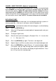
DISPLAYS IN THE PARTITIONING MASTER MODE ARMED and READY STATUS The LCD screen will display the Armed and Ready status of ALL eight (8) partitions if any or all of the areas is armed or not ready. Ready Armed 12345678 1234-678 System Ready Type code to arm This display is reflecting all 8 areas are Ready, and Area 5 is disarmed. NOTE: If a number is flashing on the Armed line, that area is armed Instant. If a number is flashing on the Ready line, that area is ready to be Force Armed.
To disarm all of these areas, press • . To arm all of these areas, press – . To toggle a single area between the armed and disarmed conditions, press [À][Area number]. For example: If Area 4 is armed, [À] [4] will disarm Area 4. If Area 4 is disarmed, [À] [4] will arm it. Press [STAY] during the exit delay to bypass all interior zones in the exit delay. To control the individual areas, refer to the following section.
V. KEYPAD CONTROL TONES (BEEPS) A sounder is built into the keypad and may sound for any of the following reasons: Beeps for all key presses. Sounds a continuous tone during the Entry delay time. Pulses when a day zone is violated while the system is disarmed. Pulses when a FIRE zone has a trouble condition. Pulses when the armed status changes and the AC power is off. Beeps 3 times for trying to arm with the “READY” light off, if “FORCE ARMING” has not been selected.
VI. SERVICE DISPLAY The following message will be displayed periodically if the security system requires service. Call your service provider promptly if this message is observed. Service Required Type r2 for help If you see this display, press r 2 One or more of the following fault messages will be displayed. Use the scroll keys • – to browse through them. To exit the service messages, press [#]-[#]. Control Box tamper (Optional) The Box Tamper circuit has activated. Control Fail to Comm.
Expansion Box tamper A box containing an expansion device has been opened. Expansion Low Battery An expansion power supply has a low battery. Expansion Over-current A short circuit of an expansion devices’ power supply has occurred. Expansion Power trouble The main power to an expansion power supply is not on. Expansion Siren trouble Open circuit has occurred on the bell or siren circuit of the expander Expansion RF Jammed A radio receiver is being jammed. (Not applicable to all controls.
VII. APPENDIX A - EVENT LOG NOTE: Your system may not have all of the features listed in this table.
DISPLAY DESCRIPTION Cancel Cancel Gnd Flt Man Test Ground Fault Manual Test Re-exit Re-Exit Output Trip Output Trip Data Lost Data Lost Walk-test End Test Cross-Trip Walk-Test End Test Cross Trip Expansion Event Partial Arm Listen In Service Start Service End Code Entry First Open Last Close Sprnklr Clock Set RF Jammed CleanMe Expansion Event Partial Arm Listen In Service Start Service End Code Entry First Open Last Close Sprinkler Clock Set RF Jammed CleanMe 24 System is disarmed and the C
VIII. EMERGENCY EVACUATION PLANS An emergency evacuation plan should be established for an actual fire alarm condition. For example, the following steps are recommended by the National Fire Protection Association and can be used as a guide in establishing an evacuation plan for your building. Draw up a floor plan of your home. Show windows, doors, stairs, and rooftops that can be used for escape. Indicate each occupant's escape routes. Always keep these routes free from obstruction.
1 2 3 4 5 6 7 8 9 10 11 12 13 14 15 16 17 18 19 20 21 22 23 24 For Service Contact 24 HOUR STAY MODE ZONE LIST ENTRY / EXIT 24 Programmed Phone Number 1: Programmed Phone Number 2: Programmed Phone Number 3: