
Installation manual


© Hills Industries 2009 Page 6
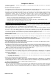
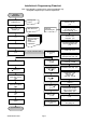
Board Installation
The metal enclosure should be installed with the door opening from the top to bottom. It
should be installed away from damp areas (e.g. bathrooms, kitchens), away from sources of
heat, dust or interference (e.g. air conditioners, washing machines, dryers, refrigerators) and
away from external walls.
Inside the enclosure there are four slots for board insertion, two on the top and two on the
bottom of the enclosure. These allow the PC board to be positioned vertically as shown in the
diagram. When you slide the board between the grooves of the slots, make sure the terminal
strip is toward the front opening (toward you) to allow for the wire connections.
Inside the enclosure several 2-holed insertion points have been constructed. This allows for
either vertical or horizontal placement of the modules. Notice that each insertion point has
two sizes of holes - a larger hole and a smaller hole.
Diagram 1: The black plastic PCB guides are grooved on one edge where the PC board will
be seated. The end with the half-moon protrusion fits into the larger hole. The smaller hole is
for the screw.
Diagram 2: Place the first black plastic PCB guide in the top insertion point, grooved edge
downward. The half-moon protrusion will be in the large hole. It does not require force to
insert. Insert one of the provided screw into the smaller hole (from inside the enclosure) to
secure it in place. A screwdriver should reach through the notch that runs the length of the
guide to tighten the screw. The second PBC guide should be positioned opposite the first
(grooved edge up) and placed in the lower insertion point, using the same procedures
described above. Once mounted, screw it in securely.
Diagram 3: The PC Board should slide freely in the grooves of both guides.
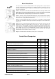
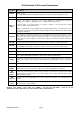
Control Panel Comparison
R8 R12 R128
Independent number of zones 8 12 16
Expandable to a maximum number of zones
(a combination of hardwired and/or wireless)
8 16 128
Anti-tamper supervision of all zones (hardwired and wireless) Yes Yes Yes
Full supervision of all expansion module and code pads Yes Yes Yes
Individual areas/partitions 1 2 8
Total number of user PIN codes (4 digit) 8 40 99
Maximum number of code pads
* Max 8 VoiceNav code pads if using intercom features
8 16 24
Code pad tampers Yes Yes Yes
Uni Arming (single button arming for full or partial mode) Yes Yes Yes
Home mode/Partial mode arming Yes Yes Yes
Automatic arming (and auto partial mode arming) Yes Yes Yes
Re-exit feature Yes Yes Yes
Real-time event history (maximum events) 185 185 185
Phone line monitor Yes Yes Yes
Fire alarm verification Yes Yes Yes
NX-1701EAU Keyless Door Entry (maximum modules) 1 2 4