
Installation manual


© Hills Industries 2009 Page 37
Feature 27 new Auxiliary Output 1-4 Special Timing
Feature 27 contains special timing option activation for the four auxiliary outputs. Segment 1 corresponds to output 1;
Segment 4 corresponds to output 4.
Hills Reliance 8 (Only) Note
new
: The Hills Reliance 8 has no Aux 3 terminal, instead Feature 27 – Segment 3 relates to
the SMOKE terminal. By default on the Hills Reliance 8, F 27 – Seg 3 – Opt 3 is off (i.e. “follow timer”) and Opt 6 is on (i.e.
0V output). Turn F 27 – Seg 3 – Opt 6 off if you wish to connect a smoke detector. When Option 6 is on = 0V output, off =
12V output on SMOKE terminal. This allows the SMOKE terminal to function as a voltage output relay. You may need to
program Feature 30 to use this feature (e.g. to open a garage door using a 4 button keyfob, add a relay to the terminals).
Hills Reliance 12 (Only) Note: On the Hills Reliance 12, the AUX 4 terminal is used as SMOKE + for two-wire smoke
detectors (see Feature 22). Or as Zone 7 for a four-wire smoke detector by default. The function cannot be changed.
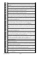
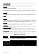
Segments 1 – 4 Outputs 1 – 4
1
On if output should be timed in minutes; Off if timed in seconds
2
On if output should latch; Off if output should be timed
(3)
On if output should stop timing upon code entry; Off if output should follow timer
4
On if output should only activate between the closing and opening time in Features 33 and 34
5
On if output should only activate between the opening and closing time in Features 33 and 34
6
On if output should be inverted
7
Reserved
8
Reserved
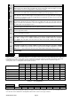
Auxiliary Output 1 – 4 Logic new
The Hills Reliance 8 has 3 auxiliary outputs (Features 28, 29, 30), Reliance 12 and Reliance 128 have 4 auxiliary outputs
(Features 28, 29, 30, 31).
Features 28, 29, 30 and 31 each set an auxiliary output (1, 2, 3, and 4 respectively) for the period of time in segment 4,
based on the two events in segments 1 and 2, and the logic value set in segment 3.
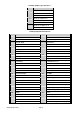
The logic value is a set of rules that apply to both Event A and Event B that must be reached before the output will trigger.
There are two rules to the logic and two states that the event can be in. The two rules are ‘AND’ or ‘OR’. The ‘AND’ rule is
used when both events have to be active for the output to trigger the “OR” rule is used when either event is active for the
output to trigger. The two states for the events are ‘true’ or ‘false’ (whether the event is currently active or whether the event
is not currently active. Use the chart on the following page to select the logic value that will apply to the relevant Auxiliary
Output.
Use the chart on the following page to select the events in segment 1 and 2 that will activate the relevant Auxiliary Output.
Program the timing in segment 4, from 0-255 (minutes or seconds, depending on data programmed in Feature 27 – Seg 1).
Programming a ‘0’ makes the output follow the event.
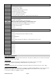
Feature 28 new Auxiliary Output 1 - Event and Time
Segments 1-4 Event A – 51 (strobe) Event B – 53 (false) new Logic – 0 (OR) new Time – 0 new
Feature 29 new Auxiliary Output 2 - Event and Time
Segments 1-4 Event A – 7 (siren) Event B – 53 (false) new Logic – 0 (OR) new Time – 0 new
Feature 30 new Auxiliary Output 3 - Event and Time
Segments 1-4 Event A – 23 (ready) Event B – 53 (false) new Logic – 0 (OR) new Time – 0 new
Event A is 39 (smoke reset) on Reliance 8 that occurs when *7 is pressed on a code pad.
Feature 31 new Auxiliary Output 4 - Event and Time
Segments 1-4 Event A – 21 (armed) Event B – 53 (false) new Logic – 0 (OR) new Time – 0 new