
Installation manual


© Hills Industries 2009 Page 17
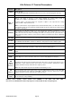
7. Service Menu - Function [2]
The service light will be “on” if the security system requires service. If the service LED is “on”, press the [] key followed by
the [2] key to determine the service condition. One or more zone LEDs will illuminate indicating what service(s) is required.
Call your service provider immediately for these problems. Below is a listing of what each LED means in a service
condition:
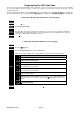
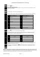
LED Problem
1
SYSTEM FAULT – Press the [1] key. The zone LED(s) illuminated corresponds to the system fault(s)
below:
LED System Fault LED System Fault
1
Over Current Fault
5
Expander Low Battery
2
Siren Trouble
6
Expander Box Tamper
3
Box Tamper
7
Expander Trouble
4
Expander Power
8
Reserved
Note: Faults 1 & 2 are global in nature and will affect all areas of a multi-area system.
Press the [#] key to return to the 1 of 8 service LEDs.
2
ZONE TAMPER – Press the [2] key and the zone LED(s) will illuminate showing the zone(s) that are
tampered. Press the [#] key to return to the 1 of 8 service LEDs.
3
ZONE LOW BATTERY – Press the [3] key. The zone LED(s) will illuminate showing which zone(s) has a
low battery. This only applies to wireless zones. Press the [#] key to return to the 1 of 8 service LEDs.
4
ZONE LOSS OF SUPERVISION – Press the [4] key and the zone LED(s) will illuminate showing which
zone(s) has loss of supervision. This only applies to wireless zones. Press [#] key to return to the 1 of 8
service LEDs.
5
ZONE TROUBLE – Press the [5] key and the zone LED(s) will illuminate showing which zone(s) has a
trouble condition. Press the [#] key to return to the 1 of 8 service LEDs.
6
TELEPHONE LINE TROUBLE/LINE CUT – This light will illuminate when the panel senses loss of phone
line.
7
FAILURE TO COMMUNICATE – This LED illuminates when there is a failure to communicate between
your system and the central station. Note: This fault is global in nature affecting all areas of a multi-area
system.
8
LOSS OF SYSTEM TIME – This LED illuminates when there has been a loss of power and your system
clock needs to be reset. See steps 5 and 6 above to program system date and time.
To exit the Service LED Mode - press the [#] key.
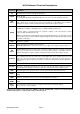
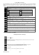
8. Changing User Codes - Function [5]
Step 1
Your system must be in the disarmed state to change user codes.
Step 2 Press the []-[5] keys
Step 3
Enter a [Master Arm/Disarm Code]
Note: Multi area systems: A user changing another user’s code must have access to all or more areas
than the user being changed.
Step 4
The ready light will flash
Step 5 Enter the 2 digit ‘user number’ (always enter 2 digit such as [0]-[3] for user 3)
Step 6
Enter the new four (4) or six (6) digit ‘user code’.
Note: To delete a user code, enter [Chime]-[Chime]-[Chime]-[Chime] for a 4-digit code,
or [Chime]-[Chime]-[Chime]-[Chime]-[Chime]-[Chime] for a 6-digit code.
Step 7
The ready light will flash indicating you are back at Step 5 above. If the code is rejected, the sounder
beeps 3 times.
Step 8
If another ‘user code’ needs to be programmed, return to Step 5
Step 9 Press the [#] key while the ready light is flashing to exit the user code programming mode.