Installation manual HILLS RELIANCE
Hills Reliance Control Panel Thank-you for choosing the Hills Reliance Control Panel! The Hills Reliance security control panel from Hills Industries represents a new approach to security system design. Drawing on experience from the world market, Hills has developed the most flexible, durable, and user-friendly control ever seen in our industry.
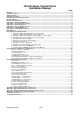
Hills Reliance Control Panel Installation Manual Page Warnings ...............................................................................................................................................................................1 Compliance Notices .............................................................................................................................................................2 Updated Features .............................................................................
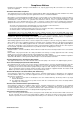
Compliance Notices Information to the Installer - Changes and modifications not expressly approved by Hills can void the user’s authority to operate the equipment. Australia & New Zealand Compliances This equipment has been tested and found to compliant with the ACA A-Tick and (NZ) Telepermit standards. These limits are designed to provide reasonable protection against interference in a residential installation.
Updated Features There are new features on the Hills Reliance product, and some which have been changed from the previous version. These have the text “new” next to the relevant sections in this manual. A summary of key updates is presented below.
Ordering Information Hills Reliance System Modules & Equipment Part # Description DAS Code NX-8-v2-HILLS Hills Reliance 128 Control Panel S4133 NX-6-v2-HILLS Hills Reliance 12 Control Panel S4142 NX-4-v2-HILLS Hills Reliance 8 Control Panel S4697 NX-1508-HILLS Vertex 8 Zone LED Code Pad S4158 NX-1516-HILLS Vertex 16 Zone LED Code Pad S4157 NX-108-HILLS 8 Zone LED Code Pad S4127 NX-116-HILLS 16 Zone LED Code Pad S4132 NX-124-HILLS 24 Zone LED Code Pad S4131 NX-148-HILLS Alphanumer
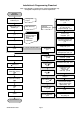
Installation & Programming Flowchart Note – This diagram is a guide for basic system programming only.
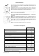
Board Installation The metal enclosure should be installed with the door opening from the top to bottom. It should be installed away from damp areas (e.g. bathrooms, kitchens), away from sources of heat, dust or interference (e.g. air conditioners, washing machines, dryers, refrigerators) and away from external walls. Inside the enclosure there are four slots for board insertion, two on the top and two on the bottom of the enclosure.
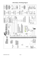
Hills Reliance 128 Wiring Diagram © Hills Industries 2009 Page 7
Hills Reliance 128 Terminal Descriptions Terminal EARTH AC Description Earth / Ground. To comply with ACA S009 & AS/NZS3000:2000. Connect to the 16.5V AC plug pack earth wire. AC input. Connect a 16.5V, 25 VA, 40 VA or 50 VA approved transformer. Built in siren driver, if used as a siren output (default), the speaker rating should be 15 Watt at 8 or 16 Ohm, or 30/40 Watt at 4, 8, or 16 Ohm, 250mA maximum load.
Hills Reliance 12 Wiring Diagram © Hills Industries 2009 Page 9
Hills Reliance 12 Terminal Descriptions Terminal EARTH AC Description Earth / Ground. To comply with ACA S009 & AS/NZS3000:2000. Connect to the 16.5V AC plug pack earth wire. AC input. Connect a 16.5V, 25 VA, 40 VA or 50 VA approved transformer. Built in siren driver, if used as a siren output (default), the speaker rating should be 15 Watt at 8 or 16 Ohm, or 30/40 Watt at 4, 8, or 16 Ohm, 250mA maximum load.
Hills Reliance 8 Wiring Diagram © Hills Industries 2009 Page 11
Hills Reliance 8 Terminal Descriptions Terminal AC Description AC input. Connect a 16.5V 1.5A approved plug pack. EARTH Earth / Ground. To comply with ACA S009 & AS/NZS3000:2000. Connect to the 16.5V AC plug pack earth wire. AUX OUT 1 Auxiliary Output Terminal, normally used to connect the negative lead of the strobe. The positive lead of the strobe can be connected to any of the positive terminals e.g. KP POS.
Main Options Areas The Hills Reliance 128 can have up to a maximum of eight separate systems (areas) with distinct reporting codes, user codes, and operating options for each system (see Features 16-21 and 37-58). The Hills Reliance 12 has up to two areas, and the Hills Reliance 8 has one area. Arm / Disarm Codes The Hills Reliance 128 can have 99 four-digit codes or 66 six-digit codes to arm/disarm the control. All codes must have the same number of digits.
Exit Error If enabled, the Hills Reliance will send an ‘Exit Error Report’ if an entry/exit zone is faulted at the instant the exit delay expires. This report will be sent along with the user number that armed the system, if the panel is not disarmed before the entry delay expires. The alarm report will also be sent. Even if this option is not enabled, the siren will sound if any entry/exit zone is faulted at the instant the exit delay expires.
Programming The LED Code Pads This section describes how to program the address and area of each code pad as well as the options that are available. The code pad address allows the panel to monitor and supervise the connected code pads and report code pad communication faults. The factory default for the Master code is [1]-[2]-[3]-[4] when using a 4-digit code or [1]-[2]-[3]-[4]-[5]-[6] for a 6-digit code.
3.
7. Service Menu - Function [2] The service light will be “on” if the security system requires service. If the service LED is “on”, press the [] key followed by the [2] key to determine the service condition. One or more zone LEDs will illuminate indicating what service(s) is required. Call your service provider immediately for these problems. Below is a listing of what each LED means in a service condition: LED Problem SYSTEM FAULT – Press the [1] key.
9. Assigning User Code Authority Levels - Function [6] Step 1 Assign user codes before assigning authority levels Step 2 Press the []-[6] key Step 3 Enter a [Master Arm/Disarm Code] Note: a user changing the authority of another user can only add or remove area authorization for areas to which they have access. Step 4 The ready light will flash Step 5 Enter the 2 digit ‘user number’ to be assigned authority. (The ready light is constant and the partial light will flash).
10. Walk Test Mode - Function [] [Chime] Step 1 Press the []-[Chime] keys Enter a [Master Arm/Disarm Code] Step 2 Now all zones become 24 hour, silent and local (non reporting zones). By faulting any zone, that zone will latch its zone light on the LED code pad, and sound the Chime. The Chime will continue to sound each time a zone is faulted. Once all zone are tested (zone lights lit on the LED code pad) go to step 3. Step 3 Enter a [Master Arm/Disarm Code] 11.
Programming The Hills Reliance Control Panel Features, Segments and Options The Hills Reliance programming structure consists of Features, Segments, and Options. Features or Feature numbers are used to locate an option or group of options. Example: Feature 6 contains the communicator format selection and Feature 16 contains area one options. Segments are contained within each feature, there are two types of segments. The first segment type is referred to as an option select segment.
Programming Data Programming Data: Programming data is always one of two types. One type of data is numerical and can take on values from 0-15 or 0-255 depending on the feature's segment. The other type of data is a Option selection type. Option selection data is used to turn options on or off. Use the following procedures when working with these two data types: Numerical Data: Numerical data is programmed by entering a number from 0-255 on the numeric keys of the system code pad.
Programming Example Figure 1 - Numerical Data (Binary) 1 2 4 7 Zone 1 LED = 1 Zone 4 LED = 8 } Zone 2 LED = 2 Zone 7 LED = 64 Data = 9 } Data = 66 Enters the previous programming “feature” To change data in a segment, enter the data followed by [] Returns to the “feature” just programmed.
Programming Feature Descriptions System Codes Feature 0 Code Requirements Feature 0, segment 1 is used to enable the 6 digit user code option. If 6-digit option is enabled, all arm/disarm codes, the ‘Go To Program Code’ and duress code are 6 digits. If this option is enabled, the default user 1 code is [1]-[2]-[3]-[4]-[5][6]. The Hills Reliance 128 has 99 four (4) digit user codes or 66 six (6) digit user codes, the Hills Reliance 12 has 40 codes, the Hills Reliance 8 has 8 codes.
Dialer Options (Features 4 – 11) Feature 4 Phone Number One (1) Segments 1-20 14 14 14 14 14 14 14 14 14 14 14 14 14 14 14 14 14 14 14 14 The first telephone number is programmed in Feature 4. ’15’ = pulse dialling - in the segment where pulse dialling should begin ’14’ indicates the end of the phone number.
Feature 8 Segments 1-20 Phone Number Three (3) 14 14 14 14 14 14 14 14 14 14 14 14 14 14 14 14 14 14 14 14 The third telephone number is programmed in Feature 8. ’15’ = pulse dialling - in the segment where pulse dialling should begin ’14’ indicates the end of the phone number.
Download Options (Features 12 – 15) Feature 12 Download Access Code Segments 1-8 1 6 0 0 0 0 0 0 Feature 12 contains the eight digit access code the panel must receive from the downloading software before the panel will permit downloading to occur. Feature 13 Number of Rings (Seg 1) / Number of Calls to Answer (Seg 2) Segments 1-2 0 0 Feature 13, segment 1 contains the number of rings the panel must detect before answering the telephone line when initiating a download session.
Feature 16 new Area 1 – Option and Report Selections Feature 16 is used to enable certain options for this area and code pads in this area. In addition, certain communicator reports are enabled in Feature 16. Each of these options can be enabled by area. For additional area information see Features 37-58 on pages 40-44. If the option selection feature for any area is left blank, that area will use this feature for the option selection. This feature contains 5 segments of 8 options each.
Area Option Descriptions AC Power / Low Battery Sounder Alert If enabled, the panel will beep the Code Pad sounder upon arming or disarming if the AC power is missing or a low battery has been detected. Answering Machine Defeat If enabled, the DL900 software calling the panel will ring (briefly), hang up and ring (briefly) again. The sequence will be repeated as many times as programmed in Feature 13. Answering machines usually answer calls after a long ring period.
Area Option Descriptions Re-exit The panel has the ability to restart the exit delay if required without disarming the system by pressing the [Exit] key while the system is running the exit delay. This option can only be used once per arming cycle. Silent Auto-Arming If enabled, the panel will Auto-Arm this area and not activate the 50 second code pad sound. This option is used when you don’t want to alert any other area of your Auto-Arm time.
Data Default Zone Configuration 4 Entry / Exit Delay 2: Partial – Forced Arming – A trip will start entry delay 2. This zone will be active in partial mode. This zone type may be faulted while arming if forced arming is enabled in the area options. 5 Entry / Exit Delay 2: Partial – Chime – Forced Arming - A trip will start entry delay 2. This zone will be active in partial mode. This zone type may be faulted while arming if forced arming is enabled in the area options.
Data Default Zone Configuration (Zones 21-31 are not reprogrammable) 21 Instant: Partial – Twin Trip – Produces an instant alarm if tripped when armed. Ignored when disarmed. This zone will be active in partial mode. This zone type will require two triggers or another zone would have to have been trigged before it will activate an alarm. 22 Instant: Partial – Group Bypass – Produces an instant alarm if tripped when armed. Ignored when disarmed.
Feature 21 Zone Area Select - Zones 9-16 Feature 21 is used to select the area(s) that zones 9-16 reside in. A zone may reside in any combination of the eight areas. If a burglary zone resides in more than one area, it will only be active when all areas are armed. A zone that resides in more than one area will be reported to its lowest area. Feature 21 has 8 segments. Segment 1 corresponds to zone 9 and Segment 8 corresponds to zone 16.
Segment 4 (1) On if Fail To Communicate report enabled 2 On if Log Full report enabled (3) On if Auto-test report enabled (4) On if Start/End programming report enabled (5) On if End Download report enabled (6) On if Sensor Low Battery report enabled (7) 8 On if Sensor Missing report enabled On if Expander Module (number) to be reported via the Contact I.D.
System Option Descriptions Enable Steady (Temporal) Siren new If enabled this option will enable the Steady (Temporal) Siren tone and disable the Evacuation Siren tone for all fire events and any zone that has this option set in its configuration group type. Expanded Contact I.D. The Hills Reliance can report all system device alarms with their individual point number if the expanded Contact I.D. reporting is enabled (see F 22 – Seg 4 – Op 8).
Feature 23 Siren / Communicator Attempt Counter Segment 1 0 Feature 23 is used to set the burglary zone siren / communicator attempt counter. The number programmed in segment 1 will determine the number of alarm activations the Hills Reliance will allow before bypassing all burglary zones (1-128) that have tripped during the arming cycle. The bypassed zones will not report trips to a base station, and the local siren or bell will not sound for these zones.
System Timer Descriptions Partial Arm Entry Time The Partial Arm Entry time is the delay time that will be allocated to all active zones in Partial Arm Mode. Fire and 24 Hour Zones will not be affected in Partial Arm Mode. The valid time selection in this segment is 10 to 255 seconds. Strobe Time The strobe time is the duration that output programmed to follow the strobe time will activate. The valid time selection in this segment is 0 to 255 hours, where ‘0’ = Latching.
Feature 27 new Auxiliary Output 1-4 Special Timing Feature 27 contains special timing option activation for the four auxiliary outputs. Segment 1 corresponds to output 1; Segment 4 corresponds to output 4. Hills Reliance 8 (Only) Note new : The Hills Reliance 8 has no Aux 3 terminal, instead Feature 27 – Segment 3 relates to the SMOKE terminal. By default on the Hills Reliance 8, F 27 – Seg 3 – Opt 3 is off (i.e. “follow timer”) and Opt 6 is on (i.e. 0V output).
Auxiliary Output Logic Selection new Data Logic 0 Event A or Event B 1 Event A and Event B 2 Not Event A or Event B 3 Not Event A and Event B 4 Event A or Not Event B 5 Event A and Not Event B 6 Not Event A or Not Event B 7 Not Event A and Not Event B Auxiliary Output Event Selection Data Event Data Event 0 Burglary Alarm 28 Expander Trouble 1 Fire Alarm 29 Dynamic Battery Test Time 2 24 Hour Alarm 30 Open Period 3 Trouble Alarm 31 Closed Period 4 Tamper Alarm 32 Lis
Note: When event 48 is programmed, it is possible to program a user code's authorization to select which output(s) a particular code will activate. When LED 8 is on for an authorization, then LEDs 1- 4 correspond to that code activating outputs 1 - 4 respectively. Refer to the code pad programming section in this manual. Feature 32 Auto-Test Control Segments 1-4 1 168 03 00 Segment 1 Program a ’0’ if the intervals are in hours. ‘1 - 8’ if in days.
Feature 36 new Days of the Week for Auto-Arming in Areas 1 - 8 Feature 36 selects which days of the week each area will auto-arm. Segment 1 is for area 1, and Segment 8 is for area 8. Requires Features 33, 34 and 35 to be programmed to determine the Open Window. If auto-arm is enabled, the panel will auto-arm the selected area at the Closing Time on the selected day. Note that there may be a few minutes of delay depending on the site and programming.
Feature 39 new Area 2 – Option and Report Selections Feature 39 is used to enable certain options that can be accessed or are visible to the user from the code pad of the system. In addition, certain communicator reports are enabled. Each of these options can be enabled by area 2. If the option selection feature for any area is left blank, that area will use Feature 16 for the option selection.
Feature 40 new Area 2 – Entry / Exit Timers Entry Time 1 Exit Time 1 Entry Time 2 Exit Time 2 30 60 30 60 Segments 1-6 Reserved new Reserved new Feature 40 sets the primary and secondary entry / exit times for area 2. If all segments in this feature are set to ‘0’, the entry / exit time for this area will follow area 1 (Feature 17). Valid entries are 10-255 seconds.
Feature 48 Area 5 – Option and Report Selections Feature 48 is used to enable certain options that can be accessed or are visible to the user from the code pad of the system. In addition, certain communicator reports are enabled. Each of these options can be enabled by area 5. If the option selection feature for any area is left blank, that area will use Feature 16 for the option selection. Refer to Feature 39 in this section for options table.
Feature 56 new Area 8 – Account Code Segments 1-6 10 10 10 10 Reserved new Reserved new Feature 56 contains the account code sent when area 8 is reported. If Feature 56 is left as default (all ‘10’s), then the account code corresponding to the phone number dialled will be used. Feature 57 Area 8 – Option and Report Selections Feature 57 is used to enable certain options that can be accessed or are visible to the user from the code pad of the system.
Feature 62 Zone Area Select - Zones 25-32 Feature 62 is used to select the area(s) that zones 25-32 reside in. A zone may reside in any combination of the eight areas. If a burglary zone resides in more than one area, it will only be active when all areas are armed. A zone that resides in more than one area will be reported to its lowest area. Feature 62 has 8 segments. Segment 1 corresponds to zone 25 and Segment 8 corresponds to zone 32.
Feature 68 new Configuration Group 1 Characteristic Select Segment 1 1 Fire (turn on if this is a fire zone) 2 24 hour (turn on for non-fire 24 hour zones) 3 Key-switch zone (normally open switch) 4 Follower (turn on for burglary zones that are Instant during non-entry times) (5) Delay 1 zone (follows timer 1 entry and exit times) 6 Delay 2 zone (follows timer 2 entry and exit times) 7 Reserved 8 Local only (turn on if this zone should not be reported) Segment 2 1 (2) On if configuration
Feature 69 Configuration Group 2 Alarm Event Code Segment 1 3 Feature 69 contains the Contact I.D. event code sent for zone configuration group 2 alarm reports. The desired event code should be chosen from the Contact I.D. Configuration Group Event Table in the Appendix section. Feature 70 new Seg 1 Configuration Group 2 Characteristic Select 5 Seg 2 2457 Seg 3 25678 Seg 4 new Seg 5 new Use ‘Configuration Group Characteristic table’ described in Feature 68, of this section.
Feature 78 new Seg 1 Configuration Group 6 Characteristic Select 4 Seg 2 257 Seg 3 25678 Seg 4 new Seg 5 new Use ‘Configuration Group Characteristic table’ described in Feature 68, of this section. Feature 79 Configuration Group 7 Alarm Event Code Segment 1 3 Feature 79 contains the Contact I.D. event code sent for zone configuration group 7 alarm reports. The desired event code should be chosen from the Contact I.D. Configuration Group Event Table in the Appendix section.
Feature 87 Configuration Group 11 Alarm Event Code Segment 1 3 Feature 87 contains the Contact I.D. event code sent for zone configuration group 11 alarm reports. The desired event code should be chosen from the Contact I.D. Configuration Group Event Table in the Appendix section. Feature 88 new Seg 1 Configuration Group 11 Characteristic Select 4 Seg 2 2578 Seg 3 245678 Seg 4 new Seg 5 new Use ‘Configuration Group Characteristic table’ described in Feature 68, of this section.
Feature 96 new Seg 1 Configuration Group 15 Characteristic Select Seg 2 25 Seg 3 25678 Seg 4 new Seg 5 new Use ‘Configuration Group Characteristic table’ described in Feature 68, of this section. Feature 97 Configuration Group 16 Alarm Event Code Segment 1 3 Feature 97 contains the Contact I.D. event code sent for zone configuration group 16 alarm reports. The desired event code should be chosen from the Contact I.D. Configuration Group Event Table in the Appendix section.
Feature 105 Configuration Group 20 Alarm Event Code Segment 1 3 Feature 105 contains the Contact I.D. event code sent for zone configuration group 20 alarm reports. The desired event code should be chosen from the Contact I.D. Configuration Group Event Table in the Appendix section. Feature 106 new Configuration Group 20 Characteristic Select Seg 1 Seg 2 2458 Seg 3 25678 Seg 4 new Seg 5 new Use ‘Configuration Group Characteristic table’ described in Feature 68, of this section.
Feature 125 new Segments 1-8 Zones 73-80 Configuration Group 16 16 16 16 16 16 16 16 Feature 125 contains the Configuration Group (zone type) for zones 73-80. Segment 1 is for zone 73, and Segment 8 is for zone 80. Feature 126 new Zone Area Select - Zones 73-80 Feature 126 is used to select the area(s) that zones 73-80 reside in. A zone may reside in any combination of the eight areas. If a burglary zone resides in more than one area, it will only be active when all areas are armed.
Feature 133 new Segments 1-8 Zones 105-112 Configuration Group 16 16 16 16 16 16 16 16 Feature 133 contains the Configuration Group (zone type) for zones 105-112. Segment 1 is for zone 105, and Segment 8 is for zone 112. Feature 134 new Zone Area Select - Zones 105-112 Feature 134 is used to select the area(s) that zones 105-112 reside in. A zone may reside in any combination of the eight areas. If a burglary zone resides in more than one area, it will only be active when all areas are armed.
Feature 155 new Days of the Week for Auto Disarm Areas 1 - 8 Feature 36 selects which days of the week each area will auto disarm at the Opening Time. Segment 1 is for area 1, and Segment 8 is for area 8. Use this feature with caution, ensure you have programmed the Open Window correctly (Feature 33, 34, 35).
Appendix 1: Reporting Zone Codes in Contact I.D. The Hills Reliance control panel has the ability to report Ademco Contact I.D. transmissions. Each report in Contact I.D. consists of an event code and the zone I.D. generating the alarm. The event code will come from the chart below and be programmed in the configuration group event code. © Hills Industries 2009 Programmed Event Code Contact I.D.
Appendix 2: Reporting Fixed Codes in Contact I.D. The table below lists the CID event codes sent for the following reports (if enabled). The number in brackets following the event is the number that will be reported as the zone number if extended Contact I.D. is enabled in the system options. Otherwise zone ‘0’ will always be reported. If there are no parentheses, the zone will be reported as ‘0’. Contact I.D.
Appendix 3: Expander Numbers for Reporting Expander Trouble The tables below list the device numbers that will be reported for each expander/code pad that has a trouble condition if expanded Contact I.D. is enabled system options.
NX-408E / NX-416E / NX-448E Wireless Receiver Address Settings Module Number Reported Switch 1 Switch 2 Switch 3 Switch 4 1st 32 ON OFF ON OFF nd 33 OFF ON ON OFF rd 34 ON ON ON OFF th 4 35 OFF OFF OFF OFF 5th 36 ON OFF OFF OFF th 37 OFF ON OFF OFF th 7 38 ON ON OFF OFF 8th 39 OFF OFF ON OFF 2 3 6 NX-507E / NX-508E Relay / Output Expanders Module Number Reported Switch 1 Switch 2 Switch 3 1st 24 ON ON OFF nd 25 OFF OFF ON rd 3 26 ON
Appendix 4: Troubleshooting System Problems Device Code Pad Problem Remedy Code pad appears dead - no lights or sounds when keys are pressed. 1. Measure the output voltage at the Aux Pwr (+) terminals. Voltage should be above 12.8 volt dc. 2. Disconnect all devices connected to Aux Pwr (+) terminal leaving only the code pad connected. 3. Check for short circuits on devices connected to Aux Pwr (+) terminals. 4. Check that AC power and battery are correctly connected to panel. 5.
System Service Light “ON” - Pressing 2 displays LED 1. Press the (1) key and observe which LED comes on to indicate one of the following: 1. Over Current Fault A partial short-circuit on the Aux Pwr, Smoke power, Horn Speaker, Strobe Screamer will cause over current faults. Removing the short from the Aux Pwr Smoke Pwr will fix the over current condition. If the short is on the horn, Strobe Screamer you must put the panel into alarm once the fault has been removed clear the over current condition.
System Service Light “ON” - Pressing 2 displays LED 4. Loss of Supervision (wireless zone only). Press the (4) key and the wireless zone(s) with Loss of Supervision will be displayed. Press the (#) key twice to exit. Service Light “ON” - Pressing 2 displays LED 5. Zone Trouble. Press the (5) key and the zone that has trouble will be displayed. Zone trouble only applies to Fire type zones. Press the (#) key twice to exit. Press 7 to reset zone trouble condition.
Installation Floor Plan Instructions 1. 2. 3. 4.
3 0 0 Go To Program Code Area and Authorisation 1 Go To Program Code Reserved On enables ‘Go To Program Code’ as an Arm Only after closing On enables ‘Go To Program Code’ as a Master code (can change user codes) On enables ‘Go To Program Code’ as an Arm/Disarm code On enables ‘Go To Program Code’ to bypass zones On enables ‘Go To Program Code’ opening and closing reports Reserved 3 4 5 6 7 8 On enables the ‘Go To Program Code’ for area #5 On enables the ‘Go To Program Code’ for area #6
Opening / Closing (alarm system off = Open, alarm system on = Close) Bypass and Bypass Restore Zone Trouble and Restore Power Trouble (AC Failure or Low Battery) and Restore Zone and Box Tampers and Restore Test Reports 3 4 5 6 7 8 6 0 6 Reserved Reserved Recent Closing / Exit Error 0 0 0 0 Segment 2 0 0 Number of calls to answer download Number of rings 15 16 25 26 Pg 26 Pg Download Control 14 14 14 14 14 14 On enables the Code Pad Medical option Multiple Code Attem
16 16 16 3 4 5 6 7 8 3 4 5 6 7 8 Area 3 Area 4 Area 5 Area 6 Area 7 Area 8 16 16 16 16 Segment 2 (Zone 10) 1 2 3 4 5 6 7 8 1 2 3 4 5 6 7 8 Area 1 Area 2 Area 3 Area 4 Area 5 Area 6 Area 7 Area 8 8 7 6 5 4 3 2 1 Segment 3 (Zone 11) Zone 9-16 Area Selection 16 Segment 1 (Zone 9) 21 Feat.
Code Pad Sounder Control On if code pad sounds upon AC Power Failure On if code pad sounds when a Low Battery is detected On if code pad sounds during Twin Trip time On if code pad sounds for Zone and Box Tampers On if code pad sounds for Medical Alarm On if code pad sounds for Expander Trouble 3 4 5 6 7 8 Segment 14 Segment 13 Segment 12 Segment 11 Segment 10 Segment 9 Segment 8 Segment 7 Segment 6 Segment 5 Segment 4 Segment 3 Segment 2 Segment 1 25 0 0 0 0 0 120 0 5 5
Segment 2 Segment 1 34 Logic for Aux Out 4 (Default Logic 0 = OR) Event A for Aux Out 4 (Default Event 21 = Armed) 0 3 168 1 0 8 0 20 0 53 0 53 Timing for Aux Out 4 (Default Timing 0 = Follow) Event B for Aux Out 4 (Default Event 53 = False) Timing for Aux Out 3 (Default Timing 0 = Follow) Event B for Aux Out 3 (Default Event 53 = False) Auto-test minute Auto-test hour (ignored if Feature 32 - Segment 1 set to 0) Auto-test hourly test interval (1-255 hours) (Feature 32 - Segment 1 mus
10 10 10 On enables the Re-exit option On enables the Force Arm option On enables the Silent Code Pad Panic On enables the Audible Code Pad Panic On enables the Code Pad Fire option On enables the Code Pad Medical option Multiple Code Attempt Tamper option 2 3 4 5 6 7 8 On enables the Autoarm In Partial option Reserved On disables Bypass for Force Arm Zones Reserved Reserved Reserved Reserved 2 3 4 5 6 7 8 Segment 5 Segment 3 Segment 1 40 8 7 6 5 4 3 2 1 8 7 6 5
10 10 10 On enables the Re-exit option On enables the Force Arm option On enables the Silent Code Pad Panic On enables the Audible Code Pad Panic On enables the Code Pad Fire option On enables the Code Pad Medical option Multiple Code Attempt Tamper option 2 3 4 5 6 7 8 On enables the Autoarm In Partial option Reserved On disables Bypass for Force Arm Zones Reserved Reserved Reserved Reserved 2 3 4 5 6 7 8 Segment 5 Segment 3 Segment 1 46 8 7 6 5 4 3 2 1 8 7 6 5
10 10 10 On enables the Re-exit option On enables the Force Arm option On enables the Silent Code Pad Panic On enables the Audible Code Pad Panic On enables the Code Pad Fire option On enables the Code Pad Medical option Multiple Code Attempt Tamper option 2 3 4 5 6 7 8 On enables the Autoarm In Partial option Reserved On disables Bypass for Force Arm Zones Reserved Reserved Reserved Reserved 2 3 4 5 6 7 8 Segment 5 Segment 3 Segment 1 52 8 7 6 5 4 3 2 1 8 7 6 5
10 10 10 10 On enables the Re-exit option On enables the Force Arm option On enables the Silent Code Pad Panic On enables the Audible Code Pad Panic On enables the Code Pad Fire option On enables the Code Pad Medical option Multiple Code Attempt Tamper option 2 3 4 5 6 7 8 Reserved Reserved Reserved Reserved 4 5 6 7 8 8 7 6 5 Reserved Reserved Reserved Reserved Segment 5 Segment 3 0 30 30 Reserved Entry Timer #2 Entry Timer #1 Area 8 - Entry / Exit Timers Segment
16 16 16 2 3 4 5 6 7 8 2 3 4 5 6 7 8 Area 2 Area 3 Area 4 Area 5 Area 6 Area 7 Area 8 16 16 16 16 Segment 2 (Zone 42) 1 2 3 4 5 6 7 8 1 2 3 4 5 6 7 8 Area 1 Area 2 Area 3 Area 4 Area 5 Area 6 Area 7 Area 8 8 7 6 5 4 3 2 1 Segment 3 (Zone 43) Zone 41-48 Area Selection 16 Segment 1 (Zone 41) 66 Feat.
Key-switch Follower Delay 1 Delay 2 Reserved Local only 3 4 5 6 7 8 Partial Mode Force Arm Group Bypass Bypass Chime Steady siren Yelping siren Code pad beep 8 7 6 5 4 3 2 1 Reserved Restore Siren / Comm Dialer Delay Twin Trip Trouble DEOL Tamper Reserved 8 7 6 5 4 3 2 1 Reserved Reserved Reserved Reserved Access Control Request to Exit Resistor Defeat Zone Activity Segment 4 Fire 24 hour Key-switch Follower Delay 1 Delay 2 Reserved Local only 1
Key-switch Follower Delay 1 Delay 2 Reserved Local only 3 4 5 6 7 8 Partial Mode Force Arm Group Bypass Bypass Chime Steady siren Yelping siren Code pad beep 8 7 6 5 4 3 2 1 Reserved Restore Siren / Comm Dialer Delay Twin Trip Trouble DEOL Tamper Reserved 8 7 6 5 4 3 2 1 Reserved Reserved Reserved Reserved Access Control Request to Exit Resistor Defeat Zone Activity Segment 4 Fire 24 hour Key-switch Follower Delay 1 Delay 2 Reserved Local only 1
Key-switch Follower Delay 1 Delay 2 Reserved Local only 3 4 5 6 7 8 Partial Mode Force Arm Group Bypass Bypass Chime Steady siren Yelping siren Code pad beep 8 7 6 5 4 3 2 1 Reserved Restore Siren / Comm Dialer Delay Twin Trip Trouble DEOL Tamper Reserved 8 7 6 5 4 3 2 1 Reserved Reserved Reserved Reserved Access Control Request to Exit Resistor Defeat Zone Activity Segment 4 Fire 24 hour Key-switch Follower Delay 1 Delay 2 Reserved Local only 1
Key-switch Follower Delay 1 Delay 2 Reserved Local only 3 4 5 6 7 8 Partial Mode Force Arm Group Bypass Bypass Chime Steady siren Yelping siren Code pad beep 8 7 6 5 4 3 2 1 Reserved Restore Siren / Comm Dialer Delay Twin Trip Trouble DEOL Tamper Reserved 8 7 6 5 4 3 2 1 Reserved Reserved Reserved Reserved Access Control Request to Exit Resistor Defeat Zone Activity Segment 4 Fire 24 hour Key-switch Follower Delay 1 Delay 2 Reserved Local only 1
Key-switch Follower Delay 1 Delay 2 Reserved Local only 3 4 5 6 7 8 Partial Mode Force Arm Group Bypass Bypass Chime Steady siren Yelping siren Code pad beep 8 7 6 5 4 3 2 1 Reserved Restore Siren / Comm Dialer Delay Twin Trip Trouble DEOL Tamper Reserved 8 7 6 5 4 3 2 1 Reserved Reserved Reserved Reserved Access Control Request to Exit Resistor Defeat Zone Activity Segment 4 Fire 24 hour Key-switch Follower Delay 1 Delay 2 Reserved Local only 1
16 16 16 2 3 4 5 6 7 8 2 3 4 5 6 7 8 Area 2 Area 3 Area 4 Area 5 Area 6 Area 7 Area 8 16 16 16 16 Segment 2 (Zone 66) 1 2 3 4 5 6 7 8 1 2 3 4 5 6 7 8 Area 1 Area 2 Area 3 Area 4 Area 5 Area 6 Area 7 Area 8 8 7 6 5 4 3 2 1 Segment 3 (Zone 67) Zone 65-72 Area Selection 16 Segment 1 (Zone 65) 124 Feat.
16 16 16 2 3 4 5 6 7 8 2 3 4 5 6 7 8 Area 2 Area 3 Area 4 Area 5 Area 6 Area 7 Area 8 16 16 16 16 Segment 2 (Zone 98) 1 2 3 4 5 6 7 8 1 2 3 4 5 6 7 8 Area 1 Area 2 Area 3 Area 4 Area 5 Area 6 Area 7 Area 8 8 7 6 5 4 3 2 1 Segment 3 (Zone 99) Zone 97-104 Area Selection 16 Segment 1 (Zone 97) 132 Feat.
16 16 16 2 3 4 5 6 7 8 2 3 4 5 6 7 8 Area 2 Area 3 Area 4 Area 5 Area 6 Area 7 Area 8 Tue Wed Thur Fri Sat Reserved 3 4 5 6 7 8 Reserved Sat Fri Thur Wed Tue Mon Sun 0 Programming Sheets v1.0.
Notes
Notes
Notes
Notes
Hills Reliance Specifications Operating Power 16.5 VAC 25, 40, or 50 VA Transformer Auxiliary Power W/ 25 VA Transformer W/ 40 or 50 VA Transformer W/ NX-320 Power Supply 12 VDC Regulated 500 mA 12 VDC Regulated 1 Amp 12 VDC Regulated 3.5 Amps Loop Resistance Standard Loop 300 Ohms Maximum 2-Wire Smokes 30 Ohms Maximum 4-Wire Smokes 300 Ohms Maximum Loop Response 500mS Built-in Siren Driver 3-tone (Steady, Yelp, Evacuation) Operating Temperature 0 to 48 degrees C LED Code Pad Dimensions 16.
Quick Start Guide Short form programming sheet for a monitored system This is not a substitute for reading the manual 1. Hard Default Panel 2. Go To Program Mode 3. Soft Default Panel Unplug battery & remove power, turn on power, Enter 971300 within 10 seconds, Wait 12 seconds Repeat *8 9713 0# 910#, Exit, Exit, [Chime], wait 12 seconds 4. Go To Program Mode 5. Change Program Code 6. Duress Code *8 9713 0# 1# n*n*n*n* # 3# n*n*n*n* # 7. 8. 9. 10. 11. 12. 13. 14.