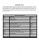
DAS NETWORX NX-16 Control/Communicator Installation Manual General Description...................................................................................................2 Ordering Information .................................................................................................2 Option Definitions...................................................................................................3-4 Programming the LED Code Pads...............................................................
NETWORX NX-16 The NetworX NX-16 from DAS represents a new approach to security systems design. Drawing on experience from the world market, DAS has developed the most flexible, durable, and user-friendly control ever seen in our industry. Featuring sophisticated software which allows up to 99 users to interface with 48 zones, 8 areas, and a host of integrated fire, access, verification, and input/output modules, all reported with the Contact I.D formats.
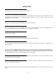
MAIN OPTIONS Areas The NX-16 can have up to a maximum of eight separate systems (Areas) with distinct reporting codes, user codes, and operating options for each system. (See Features 16-21 and 37-58) Arm / Disarm Codes The NX-16 can have 99 four-digit codes or 66 six-digit codes to arm/disarm the control. All codes must have the same number of digits. User codes are programmed and viewed from the code pad functions [*] 5 and [*] 6.
Exit Error If enabled, the NX-16 will send an "Exit Error Report" if an entry/exit zone is faulted at the instant the exit delay expires. This report will be sent along with the user number that armed the system, if the panel is not disarmed before the entry delay expires. The alarm report will also be sent. Even if this option is not enabled, the siren will sound if any entry/exit zone is faulted at the instant the exit delay expires.
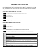
PROGRAMMING THE NX-16 LED CODE PADS This section describes how to program the address and area of each code pad as well as the options that are available. The address of the code pad is important because this is how the panel supervises the code pads. The factory default for the Master code is [1]-[2]-[3]-[4] when using a 4-digit code or [1]-[2]-[3]-[4]-[5]-[6] for a 6-digit code.
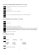
SETTING THE LED CODE PAD NUMBER AND AREA OPTIONS- Function [9][4] Step 1 Your system must be in the Disarmed state to program the code pad settings. Step 2 Press the [r] key. Step 3 Press the [9]-[4] key. Step 4 Enter the [program code]- The "Service" LED will flash.
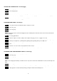
SETTING THE SYSTEM CLOCK - Function [9][7] Step 1 Press the [r] key . Step 2 Press the [9]-[7] keys. Step 3 Enter the “Master Code”. Step 4 Enter the “hour code” which must be two (2) digits. Note: The clock is a 24 hour clock. Example: 12.00 am would be entered as [0]-[0], 7.00 AM would be entered as [0]-[7], and 5.00 PM would be entered as [1]-[7]. Step 5 Enter the “minutes code” which must be two (2) digits. Example: 7 minutes after would be entered [0] [7].
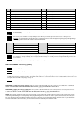
LED ATTRIBUTES IF LED 8 IS OFF LED ATTRIBUTES IF LED 8 IS ON 1 Reserved 1 Activate output #1 2 Arm Only 2 Activate output # 2 3 Arm Only After Close Window 3 Activate output # 3 4 Master arm/disarm (can program other codes) 4 Activate output # 4 5 Arm/disarm code 5 Arm/disarm 6 Allowed to bypass zones (see Feature 23) 6 Bypass Zones 7 Code will send open / close reports 7 Open / Close Reporting 8 If this LED is on, LEDs 1-7 will use the chart to the right 8 If this LED is
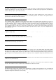
PROGRAMMING THE NX-16 CONTROL The NX-16 programming structure consists of Features, Segments, and Options. FEATURES: or Feature Numbers are used to locate an Option or Group of Options. E.G. Feature 6 contains the communicator format selection and Feature 16 contains Area one Options. SEGMENTS: are contained within each Feature, there are two types of segments. The first segment type is referred to as an Option select segment. This segment type contains up to eight Options which can be toggled On or Off.
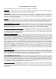
PROGRAMMING THE NX-16 CONTROL NUMERICAL DATA: Numerical data is programmed by entering a number from 0-255 on the numeric keys of the system code pad. To view the data in a feature, a binary process is used. With this process, the LED’s for zones 1 through 8 are utilized, and the numeric equivalents of their illuminated LED’s are added together to determine the data in a programming feature.
(Programming Example) 11
TERMINAL DESCRIPTION TABLE TERMINAL DESCRIPTION EARTH Earth Ground. Connect to a cold water pipe or a 1 to 3 metre driven rod. AC AC input. Connect to a 16.5V 25, 40 or 50 VA approved transformer. BELL + & BELL - If used as a siren output(default), the speaker rating should be 15 watt at 8 or 16 ohm, or 30/40 watt at 4, 8, or 16 ohms. If voltage output is selected in Feature 37, this output becomes voltage output, 12VDC, 1 Amp maximum load. NOTE: A 3.
FEATURE 0 CODE REQUIREMENTS Feature 0, segment 1 is used to enable the 6 digit user code option. If 6-digit option is enabled, all arm/disarm codes, the "Go To Program Code" and duress code are 6 digits. If this option is enabled, the default user 1 code is [1]-[2]-[3]-[4]-[5]-[6]. The NX-16 has 99 four (4) digit user codes or 66 six (6) digit user codes.
FEATURE 4 SEGMENTS 1-20 PHONE NUMBER 0NE (1) 14 14 14 14 14 14 14 14 14 14 14 14 14 14 14 14 14 14 14 14 The first telephone number is programmed in Feature 4. A "14" indicates the end of the phone number. Delays of four seconds can be programmed at any point in the phone number by programming a "13" in the appropriate segment. If pulse dialing is desired, program a "15" in the segment where pulse dialing should begin. Program an “11" for a “r” and a “12" for a “#”.
FEATURE 8 PHONE NUMBER THREE (3) SEGMENTS 1-20 14 14 14 14 14 14 14 14 14 14 14 14 14 14 14 14 14 14 14 14 The third telephone number is programmed in Feature 8. A "14" indicates the end of the phone number. Delays of four seconds can be programmed at any point in the phone number by programming a "13" in the appropriate segment. If pulse dialing is desired, program a "15" in the segment where pulse dialing should begin. Program an “11" for a “r” and a “12" for a “#”.
FEATURE 12 DOWNLOAD ACCESS CODE SEGMENTS 1-8 1 6 0 0 0 0 0 0 Feature 12 contains the eight digit access code the NX-16 must receive from the downloading software before the panel will permit downloading to occur. FEATURE 13 NUMBER OF RINGS (SEG 1) / NUMBER OF CALLS TO ANSWER (SEG 2) SEGMENTS 1-2 0 0 Feature 13, segment 1 contains the number of rings the NX-16 must detect before answering the telephone line when initiating a download session. A value of 1 to 15 can be entered in this segment.
FEATURE 16 AREA 1 - OPTIONS Feature 16 is used to enable certain options that can be accessed or are visible to the user from the code pad of the system. In addition, certain communicator reports are enabled in Feature 16. Each of these options can be enabled by area. For additional area information see Features 37-58 on pages 19-21. If the option selection feature for any area is left blank, that area will use this feature for the option selection. This feature contains 3 segments of 8 options each.
AREA OPTIONS TABLE Code Pad Tamper If enabled, the NX-16 will disable the Code Pad for 60 seconds and communicate a tamper signal to the central station if 30 key-presses are entered without producing a valid code. The Code Pad sounder will remain functional. Exit Error If enabled, the NX-16 will send an "Exit Error Report" if an entry/exit zone is faulted at the instant the exit delay expires.
FEATURE 18 SEGMENTS 1-8 ZONES 1-8 CONFIGURATION GROUP 1 3 16 16 16 16 16 16 Feature 18 contains the Configuration Group (Zone type) for zones 1-8. Segment 1 is for zone 1, and Segment 8 is for zone 8. Refer to the “Default Zone Configuration” table in this section for zone type selections. FEATURE 19 ZONE AREA SELECT - ZONES 1-8 Feature 19 is used to select the area(s) that zones 1 - 8 reside in. A zone may reside in any combination of the eight areas.
DEFAULT ZONE CONFIGURATIONS TABLE Zones can be programmed to be one of thirty different zone configurations (Zone Types). Configurations 1 to 20 can be modified in the configuration group section of this manual. Configuration groups 21 to 30 are factory set and cannot be altered. Choose one of the 30 default zone configurations to program into each of the zone configuration segments in Features 18, 20 59 61 63 and 65. Study this table for the appropriate zone configuration group for each zone.
DATA DEFAULT ZONE CONFIGURATION ZONE "14" HANDOVER: Partial - Twin Trip - Group Isolate - Forced Arming - Interior zone that follows the entry delay zones. Instant alarm type unless an entry zone if faulted first. This zone will be active in partial mode. This zone type may be faulted while arming if forced arming is enabled in the area options. This zone type will require two triggers or another zone would have to have been trigged before it will activate an alarm.
FEATURE 22 SYSTEM OPTIONS Feature 22 is used to enable various system option and reporting options. SEGMENT 1 (1) 2 3 4 5 (6) 7 (8) SEGMENT 2 1 2 3 4 5 (6) 7 (8) SEGMENT 3 (1) (2) (3) (4) (5) (6) 7 (8) SEGMENT 4 (1) (2) (3) (4) (5) (6) (7) 8 SEGMENT 5 (1) 2 3 4 5 6 7 8 On if siren sounds for "Telephone Line Cut" when armed On if siren sounds for "Telephone Line Cut" when disarmed On if siren blast at arming – ( A siren chirp when any area is armed.
FEATURE 23 SIREN / COMMUNICATOR ATTEMPT COUNTER SEGMENT 1 0 Feature 23 is used to set the burglary zone siren / communicator attempt counter. The number programmed in segment 1 will determine the number of alarm activations the NX-16 will allow before bypassing all burglary zones (1-48) which have tripped during the arming cycle. The bypassed zones will not report trips to a base station, and the local siren or bell will not sound for these zones.
SYSTEM OPTIONS TABLE First To Open / Last To Close If enabled, the NX-16 will only send a closing report when the last area is armed. NOTE: the last area to arm must have open/close reports enabled. The NX-16 will only send an opening report when the first area is disarmed. NOTE: The first area to disarm must have open/close reports enabled. Force Arm Bypass Reports If enabled, the NX-16 restricts bypass reports when zones are forced armed.
FEATURE 25 SYSTEM TIMERS Feature 25 contains the duration of various system timing functions. Example: If you desire the duration of the Strobe time to be 48 hours, you should program [4] [8] [r] in segment 2 of this feature. The [4] [8] is the number of hours, and the [r] stores the data and moves to the next segment of this feature.
FEATURE 26 AUXILIARY OUTPUT 1-4 AREA SELECTION Feature 26 is used to select which area(s) the events must occur in before the output will activate. Feature 26 has 4 segments. Segment 1 corresponds to output 1, and Segment 4 corresponds to output 4.
FEATURE 31 AUXILIARY OUTPUT 4 - EVENT AND TIME SEGMENTS 1-2 OUTPUT EVENT - 21 OUTPUT TIME - 0 Feature 31 sets the output event and output active time for auxiliary output four (4). Use the chart in this section to select the event in segment 1, that will activate Auxiliary Output 4. Program the timing in segment 2, from 0-255 (minutes or seconds, depending on data programmed in Segment 1, Feature 27). Programming a "0" makes the output follow the event.
FEATURE 32 SEGMENTS 1-4 SEGMENT 1 SEGMENT 2 SEGMENT 3 SEGMENT 4 AUTO-TEST CONTROL 7 168 03 00 Program a 0" if the intervals are in hours. “1 - 8" if in days.
FEATURE 37 SEGMENTS 1-4 AREA 1 ACCOUNT CODE 10 10 10 10 Feature 37 contains the account code sent when area 1 is reported. If Feature 37 is left un-programmed (all “10"s), then the system account code (Feature 5) will be used. FEATURE 38 SEGMENTS 1-4 AREA 2 ACCOUNT CODE 10 10 10 10 Feature 38 contains the account code sent when area 2 is reported. If Feature 38 is left un-programmed (all “10"s), then the system account code (Feature 5) will be used.
FEATURE 41 SEGMENTS 1-4 AREA 3 ACCOUNT CODE 10 10 10 10 Feature 41 contains the account code sent when area 3 is reported. If Feature 41 is left un-programmed (all “10"s), then the system account code (Feature 5) will be used. FEATURE 42 AREA 3 - OPTION AND REPORT SELECTIONS Feature 42 is used to enable certain options that can be accessed or are visible to the user from the code pad of the system. In addition, certain communicator reports are enabled in Feature 16.
FEATURE 48 AREA 5 - OPTION AND REPORT SELECTIONS Feature 48 is used to enable certain options that can be accessed or are visible to the user from the code pad of the system. In addition, certain communicator reports are enabled in Feature 16. Each of these options can be enabled by area. If the option selection feature for any area is left blank, that area will use Feature 16 for the option selection. REFER TO FEATURE 39 IN THIS SECTION FOR OPTIONS TABLE.
FEATURE 55 AREA 7 - ENTRY / EXIT TIMERS SEGMENTS 1-4 ENTRY TIME 1 - 0 EXIT TIME 1 - 0 ENTRY TIME 2 - 0 EXIT TIME 2 - 0 Feature 55 sets the primary and secondary entry / exit times for area 7. If all segments in this Feature are set to “0”, the entry / exit time for this area will follow area 1 (Feature 17). Valid entries are 10-255 seconds FEATURE 56 SEGMENTS 1-4 AREA 8 ACCOUNT CODE 10 10 10 10 Feature 56 contains the account code sent when area 8 is reported.
FEATURE 59 ZONES 17-24 CONFIGURATION GROUP SEGMENTS 1-8 16 16 16 16 16 16 16 16 Feature 59 contains the Configuration Group (Zone type) for zones 1-8. Segment 1 is for zone 17, and Segment 8 is for zone 24. FEATURE 60 ZONE AREA SELECT - ZONES 17-24 Feature 60 is used to select the area(s) that zones 17-24 reside in. A zone may reside in any combination of the eight areas. If a burglary zone resides in more than one area, it will only be active when all areas are armed.
FEATURE 64 ZONE AREA SELECT - ZONES 33-40 Feature 64 is used to select the area(s) that zones 33-40 reside in. A zone may reside in any combination of the eight areas. If a burglary zone resides in more than one area, it will only be active when all areas are armed. A zone that resides in more than one area will be reported to its lowest area. Feature 64 has 8 segments. Segment 1 corresponds to zone 33 and Segment 8 corresponds to zone 40.
Features 67-106 are used to change the zone configurations as listed in the Default Zone Configuration Table in Zones 1 to 16 configuration section. These features are considered advanced programming and should only be changed with a thorough understanding of the operation of each bit. FEATURE 67 CONFIGURATION GROUP 1 ALARM EVENT CODE SEGMENT 1 3 Feature 67 contains the Contact I.D event code sent for zone configuration group 1 alarm reports. The desired event code should be chosen from the Contact I.
FEATURE 73 CONFIGURATION GROUP 4 ALARM EVENT CODE SEGMENT 1 3 Feature 73 contains the Contact I.D event code sent for zone configuration group 4 alarm reports. The desired event code should be chosen from the Contact I.D Configuration Group Event Table in the Appendix section. FEATURE 74 CONFIGURATION GROUP 4 CHARACTERISTIC SELECT SEGMENT 1 6 SEGMENT 2 2578 SEGMENT 3 25678 Use "Configuration Group Characteristic table" described in Feature 68, of this section.
FEATURE 85 CONFIGURATION GROUP 10 ALARM EVENT CODE SEGMENT 1 3 Feature 85 contains the Contact I.D event code sent for zone configuration group 10 alarm reports. The desired event code should be chosen from the Contact I.D Configuration Group Event Table in the Appendix section. FEATURE 86 CONFIGURATION GROUP 10 CHARACTERISTIC SELECT SEGMENT 1 4 SEGMENT 2 2457 SEGMENT 3 245678 Use "Configuration Group Characteristic table" described in Feature 68, of this section.
FEATURE 97 CONFIGURATION GROUP 16 ALARM EVENT CODE SEGMENT 1 3 Feature 97 contains the Contact I.D event code sent for zone configuration group 16 alarm reports. The desired event code should be chosen from the Contact I.D Configuration Group Event Table in the Appendix section. FEATURE 98 SEGMENT 1 CONFIGURATION GROUP 16 CHARACTERISTIC SELECT SEGMENT 2 258 SEGMENT 3 25678 Use "Configuration Group Characteristic table" described in Feature 68, of this section.
Segment 1 1 2 3 9 Enables six digit code option. All arm/disarm/Go To Program codes require six digits. Requires valid user code entry for [*][9][8] and [*][9][9] functions to work.
14 14 14 14 14 14 14 14 14 14 14 14 14 14 14 14 14 14 14 14 10 10 10 10 14 14 14 14 14 14 14 14 14 14 14 14 14 14 14 14 14 14 14 14 14 14 14 14 14 14 14 14 14 14 14 14 14 14 14 14 14 14 14 14 0 Segment 1 Segment 2 1 2 3 4 5 6 7 8 1 2 3 4 5 6 7 8 Alarms Restores Open / Close Bypass Zone Trouble Power Trouble (AC Failure or Low Battery) Tampers Test Reports System Trouble (siren / phone / expander / short circuit / earth fault) Failure to C
6 Segment 1 Dial attempts 0 Segment 2 1 6 0 Reserved 0 0 0 0 0 0 Segment 1 Segment 2 Number of rings 0 Number of calls to answer Segment 1 1 2 3 4 5 6 7 8 Enables two call answering machine defeat RESERVED Requires callback before downloading Shutdown control panel Lock out local programming Lock out communicator programming Lock out download section Enables callback at autotest interval 14 14 14 14 14 14 14 14 14 14 14 14 14 14 14 14 14 14 14 14 42
Segment 1 Segment 2 Segment 3 1 2 3 4 5 6 7 8 1 2 3 4 5 6 7 8 1 2 3 4 5 6 7 8 Quick-Arm Re-Exit Force Arm Silent Panic Audible Panic Fire Medical Multi Code Attempt Tamper LED extinguish enable Require user code for bypassing zones Bypass sounder alert AC power/low battery sounder alert Enables bypass toggle Enables silent auto arm Enables universal arming Enables one key partial mode disarming Open/Close Bypass Restore Trouble Tamper Cancel Recent Closing Exit Error 30 Segment 1 (Entry Time #1)
0 Segment 1 1 2 3 4 5 6 7 8 Code Pad sounds for Telephone Line Cut when in the Armed state Code Pad sounds for Telephone Line Cut when in the Disarmed state Code Pad sounds upon AC Power Failure Code Pad sounds upon Low Battery Detection Code Pad sounds during Twin Trip Code Pad sounds for Tamper Alarm Code Pad sounds for Medical Alarm Code Pad sounds for Expander Trouble 20 Segment 1 Partial Arm Entry Time (0 - 255 seconds) 0 Segment 2 Strobe Time (0 - 255 hours) 2 Segment 3 Dynamic Battery Test D
SEGMENT 1 SEGMENT 2 SEGMENT 3 SEGMENT 4 1 2 3 4 5 6 7 8 AREA 1 AREA 2 AREA 3 AREA 4 AREA 5 AREA 6 AREA 7 AREA 8 1 2 3 4 5 6 7 8 1 2 3 4 5 6 7 8 1 2 3 4 5 6 7 8 SEGMENT 1 SEGMENT 2 SEGMENT 3 SEGMENT 4 Auxiliary output timed in minutes Auxiliary output to latch Auxiliary output to stop timing upon user code entry Auxiliary output to activate only between closing and opening time Auxiliary output to activate only between opening and closing time Invert auxiliary output (0 volts going to 12 volts when act
1 Segment 1 Program a "0" if the intervals are in hours, a "1 - 8" if in days. 1 = SUN, 7 = SAT, and 8 = DAILY.
10 10 10 10 10 10 10 10 Segment 1 Segment 2 Segment 3 1 2 3 4 5 6 7 8 1 2 3 4 5 6 7 8 1 2 3 4 5 6 7 8 Quick-Arm Re-Exit Force Arm Silent Panic Audible Panic Code Pad Fire Code Pad Medical Multi Code Attempt Tamper LED extinguish enable Require user code for bypassing zones Bypass sounder alert AC power/low battery sounder alert Enables bypass toggle Enables silent auto arm Enables universal arming Enables one key partial mode disarming 0 Segment 1 10 10 10 Bypass Restore Trouble Tamper
10 10 10 10 Segment 1 Segment 2 Segment 3 1 2 3 4 5 6 7 8 1 2 3 4 5 6 7 8 1 2 3 4 5 6 7 8 Quick-Arm Re-Exit Force Arm Silent Panic Audible Panic Code Pad Fire Code Pad Medical Multi Code Attempt Tamper LED extinguish enable Require user code for bypassing zones Bypass sounder alert AC power/low battery sounder alert Enables bypass toggle Enables silent auto arm Enables universal arming Enables one key partial mode disarming 0 Segment 1 10 10 10 Restore Trouble Tamper Cancel Recent Closing E
10 10 10 10 Segment 1 Segment 2 Segment 3 1 2 3 4 5 6 7 8 1 2 3 4 5 6 7 8 1 2 3 4 5 6 7 8 Quick-Arm Re-Exit Force Arm Silent Panic Audible Panic Code Pad Fire Code Pad Medical Multi Code Attempt Tamper LED extinguish enable Require user code for bypassing zones Bypass sounder alert AC power/low battery sounder alert Enables bypass toggle Enables silent auto arm Enables universal arming Enables one key partial mode disarming 0 Segment 1 10 10 10 Restore Trouble Tamper Cancel Recent Closing E
10 10 10 10 Segment 1 Segment 2 Segment 3 1 2 3 4 5 6 7 8 1 2 3 4 5 6 7 8 1 2 3 4 5 6 7 8 Quick-Arm Re-Exit Force Arm Silent Panic Audible Panic Code Pad Fire Code Pad Medical Multi Code Attempt Tamper LED extinguish enable Require user code for bypassing zones Bypass sounder alert AC power/low battery sounder alert Enables bypass toggle Enables silent auto arm Enables universal arming Enables one key partial mode disarming 0 Entry Time #1 Segment 2 A R E A 1 A R E A 2 A R E A 3 A R E A
16 16 16 16 16 16 16 16 SEGMENT 1 ZONE 25 A R E A 1 A R E A 2 A R E A 3 A R E A 4 A R E A 5 A R E A 6 A R E A 7 A R E A 8 16 16 16 A R E A 1 A R E A 2 A R E A 3 A R E A 4 A R E A 5 A R E A 6 A R E A 7 A R E A 8 16 1 2 3 4 5 6 7 8 16 16 A R E A 1 A R E A 2 A R E A 3 A R E A 4 A R E A 5 A R E A 6 A R E A 7 A R E A 8 16 16 16 16 16 16 SEGMENT 2 SEGMENT 3 ZONE 26 ZONE 27 SEGMENT 4 ZONE 28 SEGMENT 5 ZONE 29 SEGMENT 6 ZONE 30 SEGMENT 7 ZONE
3 Segment 1 Segment 2 Segment 3 1 2 3 4 5 6 7 8 1 2 3 4 5 6 7 8 1 2 3 4 5 6 7 8 Fire (enable for fire zone) 24 Hour Keyswitch zone Handover Delay 1 zone Delay 2 zone Interior Local Only Code Pad audible on alarm Yelping siren on alarm Steady siren on alarm Chime Bypassable Group Shunt Force armable Entry Guard 53 Fast Loop Response Double end of line tamper zone Trouble zone (Day zone) Twin Trip Dialer delay zone Swinger zone Restore reporting Listen-In
APPENDIX 1 REPORTING ZONE CODES IN CONTACT I.D The NX-16 has the ability to report Ademco Contact I.D transmissions. Each report in Contact I.D consists of an Event Code and a Zone I.D. The zone I.D is the zone that created the alarm. The event code will come from the chart below and be programmed in the configuration group event code. Programmed Event Code Contact I.
APPENDIX 2 REPORTING FIXED CODES IN CONTACT I.D The table below list the event codes sent for the following reports (if enabled) when using CONTACT I.D. The number in parentheses following the event is the number that will be reported as the zone number if extended Contact I.D is enabled in the system options. Otherwise the zone will always be zero “0”. If there are no parentheses, the zone will also be zero “0”. REPORT CONTACT I.
APPENDIX 3 EXPANDER NUMBERS FOR REPORTING EXPANDER TROUBLE The tables below list the device numbers that will be reported for each expander/code pad that has a trouble condition if expanded Contact I.
SPECIFICATIONS OPERATING POWER 16.5 VAC 25, 40, or 50 VA Transformer AUXILIARY POWER W/25 VA Transformer W/40 or 50 VA Transformer W/NX-320 Power Supply 12 VDC Regulated 500 mA 12 VDC Regulated 1 AMP 12 VDC Regulated 3.5 AMPS LOOP RESISTANCE Standard Loop 2-Wire Smokes 300 Ohms Maximum 30 Ohms Maximum BUILT-IN SIREN DRIVER 2-tone (Steady and Yelp) LOOP RESPONSE Selectable 50mS or 500mS OPERATING TEMPERATURE 32 to 120 degrees F LED CODE PAD DIMENSIONS 16.25cm Wide 10.15cm High 2.