
Installation guide
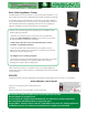
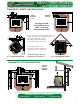


PELLET VENT TYPE
PELLET VENT MUST MAINTAIN A
MINIMUM 3” CLEARANCE TO ANY
COMBUSTIBLE (INSTALL VENT AT
CLEARANCES SPECIFIED BY THE
VENT MANUFACTURER)
DO NOT CONNECT THE
PELLET VENT TO A VENT
SERVING ANY OTHER
APPLIANCE OR STOVE
Pellet venting must be approved 3” or 4” diameter type PL or L. You must vent your stove directly to the
outside or connect to a factory built type ‘A’ chimney using an adaptor or ‘All Fuel’ stainless steel chimney
liner for masonry fireplace installations.
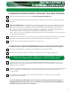
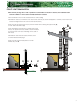
PELLET VENT INSTALLATION
Termination must exhaust above the air inlet elevation and parallel or above the exhaust output of the
pellet appliance. It is recommended that at least 3 feet of vertical pipe be installed to create natural draft.
This is to help prevent the possibility of smoke or odor during appliance shut down.
* If installing into an existing class A chimney, have the chimney cleaned and inspected by an authorized
professional before proceeding with your vent installation.
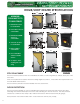
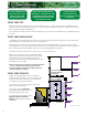
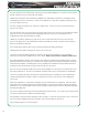
PELLET VENT DISTANCE
Maximum venting height is 33 feet. Maximum
horizontal offset is 10 feet. Use no more than 180
of elbows (eg. 2 x 90 elbows, or 2 x 45 elbows &
1 x 90 elbow, etc) plus termination.
Vent must have a support bracket every 5 feet
when on the exterior wall.
Vent height and run MUST NOT
exceed the distance shown in the
unshaded region of the chart.
To achieve optimum performance,
KEEP VENT RUNS AS SHORT AS
POSSIBLE, especially on horizontal
installations.
o
oo
o
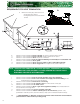
Horizontal sections must have a 1/4” rise every 12” of travel after 3 feet.
Pellet vent connections must be sealed with high
temperature RTV silicone and/or screwed together
with a least 3 x 3/8” long stainless steel screws.
Seal each vent section by injecting a liberal amount
of this silicone into the gap.
NOTE: The first joint on the stove is the most important
to seal. Also, factory seals may leak smoke.
The silicone MUST cure for at least 24 hours prior to
first time appliance startup.
Use 4” diameter venting if vent or vent liner height is over 15 feet or if the installation is over 4000 feet above
sea level.
DO NOT INSTALL A
FLUE DAMPER IN THE
EXHAUST VENTING SYSTEM
OF THIS UNIT
EXHAUST
SYSTEMS
6
Use Diameter “PL” Vent
If venting outside of
shaded area.
4”
0’
0’
5’
10’
5’
15’
20’
25’
30’
33’
Use or Diameter
“PL”Vent,ifventingin
shaded area.
3” 4”
(diagram not to scale)