
Full Product Manual


Page 10
For technical questions, please call 877.432.6627
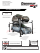
Line up runway and
drive up ramp tie
plate and bolt in
position.
Line up runway and
front tire stop plate
and bolt in position.
Fig. 6 Fig. 7
STEP 3
(Runway Installation)
1.
Locate the runway with the cylinder attached
underneath. This runway will be located adja-
cent the column with power unit bracket
attached.
2.
Position the 1/2" holes on the side of the run-
way near the power unit location. (See Fig. 5)
3.
Line up the front of the cylinder runway with
the
cross bar bolt holes, then temporarily bolt
in
position using the M14 x 100mm hex bolt,
nut and washers making sure to pass bolts
through the front tire stops. (See Fig. 7)
4.
Line up the rear of the cylinder runway with
the cross bar bolt holdes, then temporarily
bolt in
position using the M14 x 100mm hex
bolt, nylon nut and washers making sure to
pass bolts through the drive up ramp
brackets. (See Fig. 6)
Match Power
Unit Post with
bracket and
Power Runway
with 1/2" holes
for routing
hoses.
Fig. 5