
Full Product Manual


FOR TECHNICAL QUESTIONS, CALL (877)432-6627
11
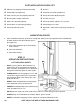
CONCRETE SPECIFICATIONS
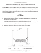
9,000-lb 2-Post Lift Models Require 6" Min. Thickness / 3,000 PSI - Steel Reinforced.
IMPORTANT NOTE:
All models MUST be installed on 3000 psi concrete only conforming to the minimum requirements shown
above. New concrete must be adequately cured by at least 28 days minimum. Dannmar lifts are supplied
with installation instructions and concrete fasteners meeting the criteria as prescribed by the American
National Standard “Automotive Lifts Safety Requirements for Construction, Testing, and Validation” ANSI/
ALI ALCTV-2011. Lift buyers are responsible for any special regional structural and / or seismic anchoring
requirements specified by any other agencies and / or codes such as the uniform building code (ubc) and
/ or international building code (ibc).
STEP 3
(Site Layout)
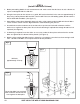
1. Determine which side will be the approach side.
2. Now determine where the Power Unit will be located. The POWERSIDE column has the power unit
mounting bracket attached to the side.
3. Once a location is determined, use a carpenters chalk line to layout a grid for the Post locations. Keep
all dimensions and squareness within 1/8" or malfunctioning of the lift can occur.
4. After the Post locations are properly marked, use a chalk or crayon to make an outline of the Posts
on the floor at each location using the Post Base Plates as a template.
5. Double check all dimensions and make sure that the layout is perfectly square.
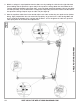
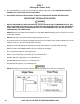
D-9X
Layout Dimensions
MODEL A B RECOMMENDED BAY DIMENSIONS
D-9/X 145" 17" 16' wide x 24' deep 12'6" tall
The Powerside column has
a power unit mounting bracket
welded here. Depending on the
location of your power supply,
this column can be positioned
on either side.