MAKING MODERN LIVING POSSIBLE www.danfoss.com/drives Quick Guide VLT® HVAC Basic Drive 132R0078 MG18A302 *MG18A302* Rev.
Contents VLT HVAC Basic Drive Quick Guide Contents 1 Quick Guide 2 1.1 Safety 2 1.1.1 Warnings 2 1.1.2 Safety Instructions 2 1.2 Introduction 3 1.2.1 Available Literature 3 1.2.2 Approvals 3 1.2.3 IT Mains 3 1.2.4 Avoid Unintended Start 3 1.2.5 Disposal Instruction 4 1.3 Installation 4 1.3.1 Before Starting Repair Work 4 1.3.2 Side-by-Side Installation 4 1.3.3 Dimensions 5 1.3.4 Electrical Installation in General 6 1.3.5 Connecting to Mains and Motor 8 1.3.6 Fuses 14 1.3.
1 1 Quick Guide VLT HVAC Basic Drive Quick Guide 1 Quick Guide CAUTION 1.1 Safety 1.1.1 Warnings WARNING High Voltage Warning The voltage of the frequency converter is dangerous whenever it is connected to mains. Incorrect installation of the motor or frequency converter may cause damage to the equipment, serious injury or death. Consequently, it is essential to comply with the instructions in this manual as well as local and national rules and safety regulations.
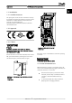
Quick Guide VLT HVAC Basic Drive Quick Guide 1 1 130BC251.10 1.2 Introduction 1.2.1 Available Literature This quick guide contains the basic information necessary for installing and running the frequency converter. If more information is needed, literature can be found on the enclosed cd or downloaded from: http://www.danfoss.com/Products/Literature/Technical +Documentation.htm 1.2.2 Approvals 1.2.3 IT Mains CAUTION IT Mains Installation on isolated mains source, i.e. IT mains. Max.
1 1 Quick Guide VLT HVAC Basic Drive Quick Guide 1.2.5 Disposal Instruction Voltage (V) Power range (kW) Min. waiting time (minutes) 3 x 200 0.25 – 3.7 4 3 x 200 5.5 – 45 15 3 x 400 0.37 – 7.5 4 3 x 400 11 – 90 15 3 x 600 2.2 – 7.5 4 3 x 600 11 – 90 15 Equipment containing electrical components must not be disposed of together with domestic waste. It must be separately collected with electrical and electronic waste according to local and currently valid legislation. 3. 1.
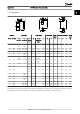
Quick Guide VLT HVAC Basic Drive Quick Guide 1 1 a A a a d f f 0D C e 130BC205.10 e 130BB614.10 B b e Enclosure Power [kW] Frame IP Class H1 IP20 0.25-1.5 kW H2 IP20 H3 IP20 H4 IP20 H5 IP20 11 kW 18.5-22 kW H6 IP20 15-18.5 kW 30-45 kW H7 IP20 22-30kW H8 IP20 37-45kW H9 130BC246.10 1.3.3 Dimensions e Height [mm] 3x 3x 3x 200-240 V 380-480 V 525-60 0V Width [mm] Depth [mm] Mounting hole [mm] Max.
Quick Guide 1 1 VLT HVAC Basic Drive Quick Guide Enclosure Clearance needed for free air passage [mm] Frame IP class Above unit Below unit H1 20 100 100 H2 20 100 100 H3 20 100 100 H4 20 100 100 H5 20 100 100 H6 20 200 200 H7 20 200 200 H8 20 225 225 H9 20 100 100 H10 20 200 200 I2 54 100 100 I3 54 100 100 I5 54 200 200 I6 54 200 200 I7 54 200 200 I8 54 225 225 Table 1.1 Clearance needed for free air passage [mm] 1.3.
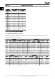
Quick Guide VLT HVAC Basic Drive Quick Guide Power (kW) 1 1 Torque (Nm) Frame IP class 3 x 525-600 V Line Motor DC connection Control terminals Earth Relay H9 IP20 2.2-7.5 1.8 1.8 not recommended 0.5 3 0.6 H10 IP20 11-15 1.8 1.8 not recommended 0.5 3 0.6 H6 IP20 22-30 4.5 4.5 - 0.5 3 0.5 H7 IP20 45-55 10 10 - 0.5 3 0.5 H8 IP20 75-90 14/241 14/241 - 0.5 3 0.5 Table 1.
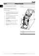
VLT HVAC Basic Drive Quick Guide 1.3.5 Connecting to Mains and Motor H1-H5 Frame IP20 200-240 V 0.25-11 kW and IP20 380-480 V 0.37-22 kW. The frequency converter is designed to operate all standard three-phased asynchronous motors. For maximum cross-section on wires please see section 1.7 General Specifications. 8 • Use a shielded/armored motor cable to comply with EMC emission specifications, and connect this cable to both the decoupling plate and the motor metal.
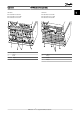
Quick Guide VLT HVAC Basic Drive Quick Guide H6 Frame IP20 380-480 V 30-45 kW IP20 200-240 V 15-18.5 kW IP20 525-600 V 22-30 kW 1 1 130BB762.10 130BB763.
VLT HVAC Basic Drive Quick Guide H8 Frame IP20 380-480 V 90 kW IP20 200-240 V 37-45 kW IP20 525-600 V 75-90 kW 130BA261.10 H9 Frame IP20 600 V 2.2-7.5 kW 130BB764.10 92 L1 93 L1 95 99 96 U 97 V 98 w M A I N S RELAY 1 RELAY 2 91 L1 95 -D C+ DC 1 2 Relays 3 Earth 4 Motor 130BA262.
VLT HVAC Basic Drive Quick Guide I N MOTOR S 95 L3 C BR - B R+ U V 91 W M L1 92 L2 93 A I L3 N 130BA264.10 +D S RELAY 2 93 H10 Frame IP20 600 V 11-15 kW RELAY 1 L2 92 +D 99 MOTO R UVW C BR - B R+ U V W - LC - L1 91 RELAY 1 99 130BA725.10 A RELAY 2 M 130BT302.12 130BA263.
VLT HVAC Basic Drive Quick Guide I2 Frame IP54 380-480 V 0.75-4.0 kW 130BC201.10 I3 Frame IP54 380-480 V 5.5-7.5 kW 130BC299.
VLT HVAC Basic Drive Quick Guide 1 1 I6 Frame IP54 380-480 V 22-37 kW 130BT325.10 130BC203.10 IP54 I2-I3 frame 130BT326.
Quick Guide VLT HVAC Basic Drive Quick Guide 130BA215.10 1 1 REL AY 1 REL AY 2 1.3.6 Fuses 90 05 03 02 04 01 9 6 9 Branch circuit protection In order to protect the installation against electrical and fire hazard, all branch circuits in an installation, switch gear, machines etc., must be short-circuit and overcurrent protected according to national/international regulations.
Quick Guide VLT HVAC Basic Drive Quick Guide Circuit Breaker UL Non UL Power kW Fuse UL Bussman Bussman Bussman Bussman n n n n Type RK5 Type RK1 Type J Type T 1 1 Non UL Max fuse Type G 3 x 200 - 240 V IP20 0.25 FRS-R-10 KTN-R10 JKS-10 JIN-10 10 0.37 FRS-R-10 KTN-R10 JKS-10 JIN-10 10 0.75 FRS-R-10 KTN-R10 JKS-10 JIN-10 10 1.5 FRS-R-10 KTN-R10 JKS-10 JIN-10 10 2.2 FRS-R-15 KTN-R15 JKS-15 JIN-15 16 3.7 FRS-R-25 KTN-R25 JKS-25 JIN-25 25 5.
Quick Guide VLT HVAC Basic Drive Quick Guide 1 1 Circuit Breaker UL Non UL Power kW Fuse UL Bussman Bussman Bussman Bussman n n n n Type RK5 Type RK1 Type J Type T Non UL Max fuse Type G 3 x 525 - 600 V IP20 2.2 KTS-R20 20 3 KTS-R20 20 5.5 KTS-R20 20 7.
VLT HVAC Basic Drive Quick Guide 130BB761.10 Quick Guide Panel PLC etc. Output contactor etc. PLC Earthing rail Cable insulation stripped Min. 16 mm2 Equalizing cable All cable entries in one side of panel Control cables Motor cable Mains-supply L1 Min. 200mm between control cable, mains cable and between mains motor cable L2 L3 PE Motor, 3 phases and Reinforced protective earth Protective earth Illustration 1.
VLT HVAC Basic Drive Quick Guide 1.3.8 Control Terminals IP54 400 V 0.75-7.5 kW 130BB622.10 130BC249.10 IP20 200-240 V 0.25-11 kW and IP20 380-480 V 0.37-22 kW: Illustration 1.4 Location of Control Terminals Place a screwdriver behind the terminal cover to activate snap. 2. Tilt the screwdriver outwards to open the cover. IP20 380-480V 30-90kW. 1. Remove the front cover. Control terminals: Illustration 1.5 shows all control terminals of the frequency converter. Applying Start (term.
Quick Guide VLT HVAC Basic Drive Quick Guide 1 1 3 Phase power input L1 L2 L3 130BB626.10 1.3.9 Electrical Overview U V W PE PE Motor UDC- Not present on all power sizes UDC+ +10Vdc 50 (+10V OUT) 0-10Vdc0/4-20 mA 53 (A IN) 0-10Vdc0/4-20 mA 54 (A IN) relay2 06 05 04 55 (COM A IN/OUT) 42 0/4-20mA A OUT / DIG OUT relay1 03 45 0/4-20mA A OUT / DIG OUT 02 20 (COM D IN) ON=Terminated OFF=Unterminated 24V (NPN) OV (PNP) 24V (NPN) OV (PNP) Bus ter.
VLT HVAC Basic Drive Quick Guide 1.4 Programming A number of information can be read from the display. 1.4.1 Programming with the Local Control Panel (LCP) 1 1.4.2 Local Control Panel (LCP) The following instructions are valid for the FC101 LCP. The LCP is divided into four functional sections. A. Alphanumeric display 2 Parameter value. Set-up number shows the active set-up and the edit setup. If the same set-up acts as both active and edit set-up, only that set-up number is shown (factory setting).
Quick Guide VLT HVAC Basic Drive Quick Guide 1 1 At power-up At the first power-up the user is asked to choose preferred language. Once selected this screen will never be shown again in the following powerups, but language can still be changed in 0-01 Language. 130BB628.10 Select Language [ 0 ] English Setup 1 1.4.
1 1 VLT HVAC Basic Drive Quick Guide At power up the user is asked to choose the prefered laguage. - the HVAC FC 101 Wizard starts Select Regional Settings [0] International Setup 1 Grid Type 200-240V/50Hz/Delta Setup 1 Select language [1] English Setup 1 Status Quick Menu Back Menu 1 On Main Menu OK Warn Alarm Off Reset Hand On Auto On Power Up Screen OK The next screen will be the Wizard screen.
Quick Guide VLT HVAC Basic Drive Quick Guide The FC101 Start-up Wizard for Open Loop Applications No & Name Range Default 0-03 Regional Settings [0] International [1] US 0 0-06 Grid Type [0] 200-240 V/50 Hz/IT-grid [1] 200-240 V/50 Hz/Delta [2] 200-240 V/50 Hz [10] 380-440 V/50 Hz/IT-grid [11] 380-440 V/50 Hz/Delta [12] 380-440 V/50 Hz [20] 440-480 V/50 Hz/IT-grid [21] 440-480 V/50 Hz/Delta [22] 440-480 V/50 Hz [30] 525-600 V/50 Hz/IT-grid [31] 525-600 V/50 Hz/Delta [32] 525-600 V/50 Hz [100] 200-24
1 1 Quick Guide No & Name VLT HVAC Basic Drive Quick Guide Range 3-03 Maximum Reference -4999-4999 Default Function 50 The maximum reference is the lowest obtainable by summing all references 5-40 Function Relay [0] Function relay See 5-40 Function Relay Alarm Select the function to control output relay 1 5-40 Function Relay [1] Function relay See 5-40 Function Relay Drive running Select the function to control output relay 2 1-29 Automatic Motor Adaption (AMA) See 1-29 Automatic Motor Ad
Quick Guide VLT HVAC Basic Drive Quick Guide 1 1 1 130BC245.
1 1 Quick Guide VLT HVAC Basic Drive Quick Guide Closed Loop Set-up Wizard No & Name Range Default 0-03 Regional Settings [0] International [1] US 0 Function 0-06 Grid Type [0]-[[132] please see Size selected Select operating mode for restart upon reconnection of the start-up wizard for open frequency converter to mains voltage after power down loop application 1-20 Motor power 0.09-110 kW Size related Enter motor power from nameplate data 1-22 Motor Voltage 50.0 - 1000.
Quick Guide VLT HVAC Basic Drive Quick Guide Motor Set-up The Quick Menu Motor Set-up guides through the needed motor parameters. No & Name Range Default Function 0-03 Regional Settings [0] International [1] US 0 0-06 Grid Type [0]-[132] please Size selected Select operating see start-up mode for restart wizard for upon open loop reconnection of application the frequency converter to mains voltage after power down 1-20 Motor power 0.12-110 kW/ 0.16-150 Hp Size related 1-22 Motor Voltage 50.
1 1 Quick Guide VLT HVAC Basic Drive Quick Guide 1.5 Parameter Overview Parameter Overview 0-** Operation / Display 0-0* Basic Settings 0-01 Language *[0] English [1] Deutsch [2] Francais [3] Dansk [4] Espanol [5] Italiano [28] Portuguese [255] No Text 0-03 Regional Settings *[0] International [1] US 0-04 Operating State at Powerup *[0] Resume [1] Forced stop, ref=old 0-06 GridType 0] 200-240 V/50 Hz/IT-grid [1] 200-240 V/50 Hz/Delta [2] Set-up 2 0-39 Display Text 3 [15] 7.50 kW - 10.
Quick Guide VLT HVAC Basic Drive Quick Guide 1 1 Parameter Overview 1-63 Slip Compensation Time Constant 0.05 - 5.00 s, * 0.10 1-64 Resonance Dampening 0 - 500%, * 100 1-65 Resonance Dampening Time Constant 0.001 - 0.050 s, * 0.005 1-7* Start Adjustments 1-71 Start Delay 0.0 - 10.0 s, * 0.
Quick Guide VLT HVAC Basic Drive Quick Guide 1 1 Parameter Overview [73] Logic rule 3 [74] Logic rule 4 [75] Logic rule 5 [80] SL digital output A [81] SL digital output B [82] SL digital output C [83] SL digital output D [160] No alarm [161] Running reverse [165] Local ref. active [166] Remote ref. active [167] Start command activ [168] Drive in hand mode [169] Drive in auto mode [193] Sleep Mode [194] Broken Belt Function [196] Fire Mode [198] Drive Bypass 5-41 On Delay, Relay 0.00 - 600.00 s, *0.
Quick Guide VLT HVAC Basic Drive Quick Guide 1 1 Parameter Overview *[0] Digital and ctrl.word [1] Digital only [2] Controlword only 8-02 Control Source [0] None *[1] FC Port 8-03 Control Timeout Time 0.1 - 6500.0s, * 1.0 8-04 Control Timeout Function *[0] Off [1] Freeze output [2] Stop [3] Jogging [4] Max.
Quick Guide VLT HVAC Basic Drive Quick Guide 1 1 Parameter Overview [29] Start timer 0 [30] Start timer 1 [31] Start timer 2 [32] Set digital out A low [33] Set digital out B low [34] Set digital out C low [35] Set digital out D low [38] Set digital out A high [39] Set digital out B high [40] Set digital out C high [41] Set digital out D high [60] Reset Counter A [61] Reset Counter B [70] Start timer 3 [71] Start timer 4 [72] Start timer 5 [73] Start timer 6 [74] Start timer 7 [100] Reset Alarm 14-** Spe
Quick Guide VLT HVAC Basic Drive Quick Guide 1 1 Parameter Overview 20-01 Feedback 1 Conversion *[0] Linear [1] Square root 20-8* PI Basic Setting 20-81 Process PI Normal/ Inverse Control *[0] Normal [1] Inverse 20-83 Process PI Start Speed[Hz] 0.0 - 200.0, * 0.0 20-84 On Reference Bandwidth 0 - 200%, * 5 20-9* PI Controller 20-91 PI Anti Windup [0] Off *[1] On 20-93 PI Proportional Gain 0.00 - 10.00, * 0.01 20-94 PI Integral Time 22-46 Maximum Boost Time 0.10 - 9999.00s, * 9999.
1 1 Quick Guide VLT HVAC Basic Drive Quick Guide Alarm/ Warning Fault Bit number Number Fault text Trip locked Cause of problem 50 AMA Calibration failed X Contact your local Danfoss supplier. 51 AMA Unom,Inom X The setting of motor voltage, motor current and motor power is presumably wrong. Check the settings. 52 AMA low Inom X The motor current is too low. Check the settings.
Quick Guide VLT HVAC Basic Drive Quick Guide 1 1 1.7 General Specifications 1.7.1 Mains Supply 3 x 200-240 V AC frequency converter Typical shaft output (kW) Typical shaft output (hp) IP20 frame Max. cable size in terminals (mains, PK2 5 0.25 0.33 H1 4/10 PK3 7 0.37 0.5 H1 4/10 PK7 5 0.75 1.0 H1 4/10 130BB632.10 motor) [mm2/AWG] Output current P1K P2K2 P3K P5K5 P7K5 P11K P15K P18K P22K P30K P37K P45K 5 7 1.5 2.2 3.7 5.5 7.5 11.0 15.0 18.5 22.0 30.0 37.0 45.0 2.0 3.0 5.0 7.5 10.0 15.0 20.0 25.0 30.
MG18A302 - VLT® is a registered Danfoss trademark Max. mains fuses RELAY 2 Max. input current RELAY 2 2.0 1.8 1.0 1.1 2.3 1.3 Intermittent (3 x 380-440 V) [A] Continuous (3 x 440-480 V) [A] Intermittent (3 x 440-480 V) [A] 2.1 2.3 1.2 1.2 2.1 2.4 1.3 1.1 2.2 1.2 0.75 1.0 H1 4/10 PK75 Continuous (3 x 380-440 V) [A] 440-480 V)[A] Intermittent (3 x 440-480 V) [A] Continuous (3 x 380-440 V)[A] Intermittent (3 x 380-440 V) [A] Continuous (3 x 0.37 0.
Output current Continuous (3 x 440-480 V) [A] Intermittent (3 x 440-480 V) [A] Continuous (3 x 380-440 V) [A] Intermittent (3 x 380-440 V) [A] Weight enclosure IP20kg] Efficiency [%], Best case/Typical 1 P1K5 1.8 2.0 1.1 2.1 1.1 1.0 1.93 1.04 P2K2 46/58 P3K0 66/83 3.7 3.4 4.07 3.7 4.8 4.4 5.4 4.85 6.1 5.5 6.9 6.3 50°C ambient temperature 46/57 P4K0 P5K5 P7K5 P11K P15K P18K P22K 8.3 7.5 9.2 8.4 11.0 10.0 12.0 10.9 13.9 12.6 15.4 14.0 21.0 19.1 23.0 20.9 26.
38 MG18A302 - VLT® is a registered Danfoss trademark Max. mains fuses Max. input current Continuous (3 x 440-480 V) [A] Intermittent (3 x 440-480 V) [A] Continuous (3 x 380-440 V )[A] Intermittent (3 x 380-440 V) [A] Intermittent (3 x 440-480 V) [A] Continuous (3 x 380-440 V) [A] Intermittent (3 x 380-440 V) [A] Continuous (3 x 440-480 V) [A] 2.9 3.2 2.0 3.9 2.3 1.8 3.5 3.7 2.1 2.3 3.4 4.1 2.4 2.1 3.7 1.5 2.0 I2 4/10 P1K5 2.2 0.75 1.
Output current Continuous (3 x 440-480 V) [A] Intermittent (3 x 440-480 V) [A] Continuous (3 x 380-440 V) [A] Intermittent (3 x 380-440 V) [A] Weight enclosure IP54kg] Efficiency [%], Best case/Typical 1 3.4 3.7 2.0 4.07 2.1 1.8 3.7 1.93 4.8 4.4 5.4 4.85 46/58 6.1 5.5 6.9 6.3 66/83 8.3 7.5 9.2 8.4 95/118 11.0 10.0 12.0 10.9 23 98 330 13.9 12.6 15.4 14.0 18.5 16.8 21.2 19.2 23.8 21.6 28.2 25.
VLT HVAC Basic Drive Quick Guide 1.7.4 Mains Supply 3 x 525-600 V AC Frequency converter Typical shaft output (kW) Typical shaft output (hp) IP20 frame P11K 11.0 15.0 H10 10/8 P15K 15.0 20.0 H10 10/8 P22K P30K 22.0 30.0 30.0 40.0 H6 H6 35/2 35/2 P45K 45.0 60.0 H7 50/1 P55K P75K P90K 55.0 75.0 90.0 70.0 100.0 125.0 H7 H8 H8 50/1 95/0 120/ (4/0) 40°C ambient temperature 4.1 5.2 9.5 11.5 19.0 23.0 36.0 43.0 65.0 87.0 105.0 137.0 4.5 5.7 10.5 12.7 20.9 25.3 39.6 47.3 71.5 95.7 115.5 150.
Quick Guide VLT HVAC Basic Drive Quick Guide 1 1 1.7.5 EMC Test Results The following test results have been obtained using a system with a frequency converter, a screened control cable, a control box with potentiometer, as well as a motor screened cable. RFI Filter Type Conduct emission.
1 1 Quick Guide VLT HVAC Basic Drive Quick Guide Protection and features • • • • • • Electronic thermal motor protection against overload. • The frequency converter is protected against earth faults on motor terminals U, V, W. Temperature monitoring of the heatsink ensures that the frequency converter trips in case of overtemperature. The frequency converter is protected against short-circuits between motor terminals U, V, W.
Quick Guide VLT HVAC Basic Drive Quick Guide Analog inputs Number of analog inputs Terminal number Terminal 53 mode Terminal 54 mode Voltage level Input resistance, Ri Max. voltage Current level Input resistance, Ri Max. current 2 53, 54 Parameter 6-19: 1 = voltage, 0 = current Parameter 6-29: 1 = voltage, 0= current 0 - 10 V approx. 10 kΩ 20 V 0/4 to 20 mA (scalable) <500Ω 29 mA Analog output Number of programmable analog outputs Terminal number Current range at analog output Max.
1 1 Quick Guide VLT HVAC Basic Drive Quick Guide All inputs, outputs, circuits, DC supplies and relay contacts are galvanically isolated from the supply voltage (PELV) and other high-voltage terminals. Surroundings Enclosure IP20 Enclosure kit available IP21, TYPE 1 Vibration test 1.0 g Max.
MAKING MODERN LIVING POSSIBLE www.danfoss.com/drives Quick Guide VLT® HVAC Basic Drive 132R0078 MG18A302 *MG18A302* Rev.