
Service manual


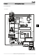


9.1.4 H9 Frame Size
x 3
DC /AC
o
C
Temp.
conv.
uC+
EEP
7 xGD
RL 1
GD
Supply
A
BR
GD
BR
FB
INV
GD
AC/DC
x3
BR
P _BRF
RL 2
RFI
_
RL 1
Inrush
SAFE
_
FB
Tmp
_
VGDS
VCC
FAN 1
CAN
A
A
Imax2 comp.
MAINS
RL 2 RL 1
RFI (
variations)
Tmp_VGDS
L 1
L 2
L 3
Inrush
RFI
_
RL 2
RFI
_
RL
1
FFB 1
Int.
fans
”Internal supply bus”
”Internal Communication”
Level
Shift
VCX (GX ) 5V
VCC (
GND
) 5V
VDD (
GND
) 24V
SMPS
Motor
U
V
W
UINV
_
P
UINV
_
N
VGD +/- 15/UDC -/-5
VGD+/- 15/UDC-/-5
RFI
_
RL
2
Brake not connected to terminal on FC101
Control Card
ACP
Isol. RS 485
D-I/O
A-I/O
MCP
LCP
Display
control
panel
130BC136.10
Illustration 9.4
Block Diagrams
VLT
®
HVAC Basic Drive Service Manual
MG90X202 - VLT
®
is a registered Danfoss trademark 99
9 9