MAKING MODERN LIVING POSSIBLE Installation Guide VLT® CANopen MCA 105 VLT® AutomationDrive FC 301/302 vlt-drives.danfoss.
Contents Installation Guide Contents 1 Introduction 2 1.1 Purpose of the Manual 2 1.2 Additional Resources 2 1.3 Product Overview 2 1.4 Approvals and Certifications 2 1.5 Disposal 3 1.6 Symbols, Abbreviations, and Conventions 3 2 Safety 4 2.1 Safety Symbols 4 2.2 Qualified Personnel 4 2.3 Safety Precautions 4 3 Installation 6 3.1 Safety Instructions 6 3.2 EMC-compliant Installation 6 3.3 Grounding 6 3.4 Cable Routing 6 3.5 Mounting 7 3.6 Setting Address Switches 8 3.
1 1 Introduction VLT® CANopen MCA 105 1 Introduction 1.1 Purpose of the Manual 1.3 Product Overview This installation guide provides information for quick installation of a VLT® CANopen MCA 105 interface in the VLT® frequency converter. The installation guide is intended for use by qualified personnel. Users are assumed to be familiar with the VLT® frequency converter, with CANopen technology, and with the PC or PLC that is used as a master in the system.
Introduction Installation Guide 1.5 Disposal Do not dispose of equipment containing electrical components together with domestic waste. Collect it separately in accordance with local and currently valid legislation. 1.
2 2 VLT® CANopen MCA 105 Safety 2 Safety WARNING 2.1 Safety Symbols The following symbols are used in this manual: WARNING Indicates a potentially hazardous situation that could result in death or serious injury. CAUTION Indicates a potentially hazardous situation that could result in minor or moderate injury. It can also be used to alert against unsafe practices. UNINTENDED START When the frequency converter is connected to AC mains, DC supply, or load sharing, the motor may start at any time.
Safety Installation Guide WARNING EQUIPMENT HAZARD 2 2 Contact with rotating shafts and electrical equipment can result in death or serious injury. • Ensure that only trained and qualified personnel perform installation, start-up, and maintenance. • Ensure that electrical work conforms to national and local electrical codes. • Follow the procedures in this manual.
3 Installation 3.1 Safety Instructions 3.4 Cable Routing See chapter 2 Safety for general safety instructions. NOTICE 3.2 EMC-compliant Installation EMC INTERFERENCE To obtain an EMC-compliant installation, follow the instructions provided in the relevant frequency converter operating instructions and design guide. Refer to the fieldbus master manual from the PLC supplier for further installation guidelines. 3.
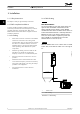
Installation Installation Guide 130BD862.10 3.5 Mounting 1. Check whether the fieldbus option is already mounted in the frequency converter. If already mounted, go to step 6. If not mounted, go to step 2. 2. Remove the LCP or blind cover from the frequency converter. 3. Use a screwdriver to remove the front cover and the LCP cradle. 4. Mount the fieldbus option. Mount the option with the connector facing up for top cable entry (see Illustration 3.
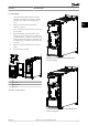
3.6 Setting Address Switches 3.7.2 Wiring Procedures NOTICE Wiring procedure for enclosure sizes A1–A3 Switch off the power supply before changing the address switches. The address change comes into effect at the next power-up. 1. Mount the fieldbus connector on the fieldbus option (CAN_L, Drain, CAN_H). For top cable entry, mount the supplied EMC bracket on top of the frequency converter with 2 screws. The address switches enable setting of baudrate and node ID: 2.
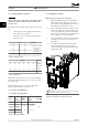
Installation Installation Guide Wiring procedure for enclosure sizes A4–A5, B1–B4, and C1–C4 Terminal Colour Name 1 – – Not used 2 CAN_L Blue CAN LOW 3 Drain (bare) Screen 4 CAN_H White CAN HIGH 5 – – Not used Push the cable through cable glands. 2. Mount the fieldbus connector on the fieldbus option ( CAN_L, Drain, CAN_H). 3. Prepare the fieldbus cable by stripping a section of the cable insulation. Keep the unshielded wire as short as possible.
Installation VLT® CANopen MCA 105 3.8 Reassembling Cover Wiring procedure for enclosure sizes D, E, and F 1. Mount the fieldbus connector on the fieldbus option (CAN_L, Drain, CAN_H). 2. Prepare the fieldbus cable by stripping a section of the cable insulation. Keep unshielded wire as short as possible. For cable specifications, refer to chapter 3.7.1 Cable Specifications. 3 3 Connect the fieldbus cable wires to the terminals according to the colour code of the wires, see Illustration 3.6. 4.
Troubleshooting Installation Guide 4 Troubleshooting 4.1 Warnings and Alarms NOTICE Refer to the relevant operating instructions for an overview of warning and alarm types and for the full list of warnings and alarms. Alarm word, warning word, and CANopen warning word are shown on the frequency converter display in hex format. When there is more than 1 warning or alarm, the sum of all warnings or alarms is shown.
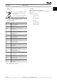
Index VLT® CANopen MCA 105 Index N A Network cabling.................................................................................... 10 Abbreviations........................................................................................... 3 Additional resources.............................................................................. 2 P Address switch.................................................................................. 8, 10 Power, applying...................................
Index MG33J402 Installation Guide Danfoss A/S © 05/2015 All rights reserved.
Danfoss can accept no responsibility for possible errors in catalogues, brochures and other printed material. Danfoss reserves the right to alter its products without notice. This also applies to products already on order provided that such alterations can be made without subsequential changes being necessary in specifications already agreed. All trademarks in this material are property of the respective companies. Danfoss and the Danfoss logotype are trademarks of Danfoss A/S. All rights reserved.