
Operating instructions

VLT
®
6000 HVAC
18
MG.60.G2.02 - VLT is a registered Danfoss Trademark
Typical Control Connection Examples
TT
TT
T
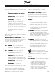
wo Feedback Signals:wo Feedback Signals:
wo Feedback Signals:wo Feedback Signals:
wo Feedback Signals:
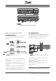
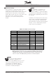
The drive processes two independent feedback
signals during closed loop operation (see Figure 6). It
can respond to the sum, difference, average,
minimum or maximum of these signals.
Set Parameter 308, Terminal 53, Analog Input
Voltage, to FEEDBACK.
Set Parameter 311, Terminal 54, Analog Input
Voltage, to FEEDBACK
Set Parameter 417, Feedback Function, for the
desired operation.
FigurFigur
FigurFigur
Figur
e 6e 6
e 6e 6
e 6 Two Feedback Signals Connection
TT
TT
T
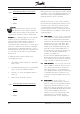
ransmitter Connection:ransmitter Connection:
ransmitter Connection:ransmitter Connection:
ransmitter Connection:
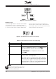
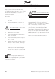
The drive’s internal 24 VDC power supply is used to
power an external 4 to 20 mA transducer (see
Figure 5).
FigurFigur
FigurFigur
Figur
e 5e 5
e 5e 5
e 5 Transmitter Connection
Set Parameter 314, Terminal 60, Analog Input
Current, to correspond to the purpose of the 4 to
20 mA signal.
Set Parameter 315, Terminal 60, Min. Scaling, to 4 mA.
Set Parameter 316, Terminal 60, Max. Scaling, to
20 mA.
Because the commons of the +24 VDC power
supply and the input reference follower have
separate circuit commons, it is necessary to
connect a jumper between terminals 39 and 55.
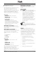
Figure 4 Electrical Control Terminals