
Instruction manual


Cascade Controller Option
Maximum is selected, the feedbacks will be equal
to or less than their associated setpoints.
Feedback 1 is associated with Setpoint 1 and
Feedback 2 is associated with Setpoint 2. The two
independent groupings are continuously monitored
to satisfy both zones requirements.
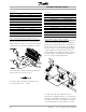
Transmitter connection to the AFD:
The transmitters are connected to the AFD in the
same way as shown above with 1 setpoint and 2
feedbacks. The feedback connected to terminal 53
is assigned to setpoint 1 and the one connected to
terminal 54 to setpoint 2. Both transmitters must
have the same output signal and range.
P
rogramming example for 2 feedback and
2 setpoint controls:
Transmitter ratings:
Supply: 15 - 30 VDC
Output: 0 - 10 V
Range: 0 - 100 Pa
The AFD is programmed to match its input to follow
the specification of the transmitter:
Programming:
Parameter Parameter Parameter
Number Description Value
100 CONFIG. MODE CLOSED LOOP
415 Ref./FDBK UNIT Pa
413 MIN. FEEDBACK 0
414 MAX. FEEDBACK 100
308 AI [V] 53 FUNCT. FEEDBACK
309 AI 53 SCALE LOW 0
310 AI 53 SCALE HIGH 100
311 AI [54] 54 FUNCT. FEEDBACK
312 AI 54 SCALE LOW 0
313 AI 54 SCALE HIGH 100
314 AI [mA] 60 FUNCT. NO OPERATION
The reference range is generally set to equal the
range of the transmitter. In this way, the setpoint
(reference) can be se
t to any value that the transmitter
can produce. If required, the reference range can be
set to a range that is narrower than the transmitter’s
range, but it cann
ot be set to a wider range.
Parameter Parameter Parameter
Number Description Value
204 MIN. REFERENCE 0
205 MAX. REFERENCE 100
In this example, load 1 requires a pressure of at
least 30 Pa and load 2 at least 60 Pa.
Parameter Parameter Parameter
Number Description Value
417 2 FEEDBACK CALC. 2 ZONE MIN
418 SETPOINT 1 30
419 SETPOINT 2 60
MG.60.I5.22 - VLT is a registered Danfoss trademark
61
Feedback Transmitter
Wiring