
Instruction manual


Cascade Controller Option
The range is determined by Quick Menu item 14
(parameter 413, Minimum Feedback)andQuickMenu
item 15 (parameter 414, Maximum Feedback). When
the pressure feedback signal originates at the far end
of the system, the drive does not need to compensate
for system pressure changes due to flow. For this
system configuration, or for two setpoint PID control,
see Alternative Programming at the end of this chapter.
Description of choice:
Set the desired feedback minimum within the
programmed minimum and maximum in Quick Menu
items 14 and 15. The process unit is selected in
Quick menu item 13, Process Units.
NOTE
Factory setting is for a single 4 - 20 mA current
signal transmitter for process feedback. In
all other cases, see instructions in Chapter
10, Feedback Transmitter W iring.
Quick Menu 030 Par. 419 Setpoint 2
(SETPOINT 2)
Value:
Feedback Min. to Feedback Max.
✭ 0.000
Function:
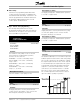
The default feedback process is used when a pressure
feedback signal is measured at the outlet of the pumps.
The cascade controller uses the feedback to estimate
the setpoint required at various rates of flow. Setpoint
2 is the maximum pressure required when the system
is running with all pumps at full capacity. A theoretical
value calculates pressure loss in the system under
maximum load. The controller adjusts the loading
based upon the number of pumps in operation.
The range is determined by Quick Menu item 14
(parameter 413, Minimum Feedback) and Quick Menu
item 15 (parameter 414, Maximum Feedback).
When the pressure feedback signal originates at
the far end of the system, the drive does not need
to compensate for system pressure changes due
to flow. For this system configuration, or for two
setpoint PID control, see Alternative Programming
at the end of this chapter.
Description of choice:
Set the desired feedback maximum within the
programmed minimum and maximum in Quick Menu
items 14 and 15. The process unit is selected in
Quick menu item 13, Process Units.
Quick Menu 032 Par. 722 Pump cycling
(PUMP CYCLING)
Value:
Enabled - Disabled
✭ Enabled
Function:
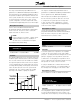
To achieve equal hours of operation, use of pumps
or fans can be cycled. Timers on the relay outputs
(relays 6, 7, 8, and 9) monitor the running hours of each
pump. In staging on, the relay with the least hours
is switched on. In destaging, the relay with the most
hours is switched off. Not operating a pump over long
time periods can create corrosion concerns.
If cycling is disabled, the controller follows the fixed
pattern of relay activation (6, 7, 8 and 9) regardless of
the running hours. Destaging is in the reverse order.
Description of choice:
Choose whether to enable or disable the function.
Quick Menu 033 Par. 319 Analog output,
terminal 42
(AO 42 FUNCTION)
Value:
Output, terminal 42
✭ Output current 4-20 mA
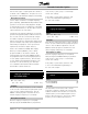
Function:
An analog/digital output is available through terminal
42 and can be programmed to show a status or an
analog value such as frequency. For the analog output,
MG.60.I5.22 - VLT is a registered Danfoss trademark
52