
Instruction manual


Cascade Controller Option
Master/Slave Cascade
Control Setup
■ Initial Setup
Instructions for programming Quick Menu items
1-20 are presented in Chapter 5, AFD Drive and
Cascade C ontro ller Card Setup. Parameters 1-20
must be programmed into the Master drive before
programming additional Master/Slave cascade
control options described below.
■ Step 1: Master drive programming
The following drive parameters are used in
programming the Master drive. Note that while the
menu items are in sequence, not each menu item
in the Quick Menu is programmed.
Quick Menu 021 Par. 712 Motor Pump
Combinations
(PUMP COMBINATION)
Value:
R6 @100%
✭ R6 @100%
R6, R7 @100%
R6-R8 @100%
R6-R9 @100%
Function:
The number of slave pumps or fans is selected
in this parameter. In Master/Slave operation,
all motors are the same size.
R6 @100% = one slave controlled by relay 6.
R6, R7 @100% = two slaves controlled by
relays 6 and 7.
R6-R8 @100% = three slaves controlled by
relays 6, 7, and 8.
R6-R9 @100% = four slaves controlled by
relays 6, 7, 8, and 9.
Description of choice:
Select the number of slave pumps or fans.
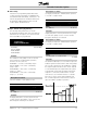
Quick Menu 023 Par. 714 SBW staging off time
(DESTAGING DELAY)
Value:
0 - 3000 sec.
✭ 30 sec.
Function:
Destaging delay time is used to prevent the fast
cycling off of the slave pumps or fans. Increase the
time if frequent switching is encountered.
Description of choice:
Set staging off delay time. In Master/Slave operation,
3 seconds is a typical value.
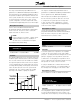
Quick Menu 024 Par. 715 SB W staging on time
(STAGING DELAY)
Value:
0 - 3000 sec.
✭ 30 sec.
Function:
Staging delay time is used to prevent the fast cycling
on of the slave pumps or fans. Increase the time
if frequent switching is encountered.
Description of choice:
Set staging on delay time. In Master/Slave operation,
3 seconds is a typical value.
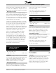
Quick Menu 029 Par. 418 Setpoint 1
(SETPOINT 1)
Value:
Feedback Min. to Feedback Max.
✭ 0.000
Function:
The default feedback process is used when a pressure
feedback signal is measured at the outlet of the pumps.
The cascade controller uses the feedback to estimate
the setpoint required at various rates of flow. Setpoint
1 is the minimum pressure required when the system
is running with only the AFD operating at full speed.
Setpoint 1 is a theoretical value that the cascade
controller uses as an internal reference to calculate
pressure loss in the system under minimum load.
The controller adjusts the internal reference based
upon the number of pumps in operation.
MG.60.I5.22 - VLT is a registered Danfoss trademark
51