
Instruction manual


Cascade Controller Option
■ Master/Slave Cascade Control Setup
■ Introduction
In Master/Slave cascade control operation, the AFD
with the cascade control option card is the Master. The
Master drive controls the speed and staging on or off
of up to four additional adjustable speed drives. The
Master drive exports a pulse signal or analog speed
signal through its output relays to the slave drives. It is
recommended that a pulse signal be used for minimum
electrical noise and for precise drive control.
The Master drive and the slave drives are programmed
for different operation, although many parameters
are set the same. The Master drive is programmed
for closed loop operation and responds to system
feedback signals to meet the needs of the system.
The slave drives are programmed for open loop
operation and receive a variable speed signal and
stop/start commands from the Master drive.
Although pump applications are highlighted in this
chapter, the procedures and settings are nearly
identical for other applications. The feedback process
setup described, assumes that a pressure feedb
ack
signal is measured at the outlet of the pumps.
P
rogramming instructions:
Instructions for programming Quick Menu items
1-20 are presented in Chapter 6, AFD and
Cascade Controller Card Setup. Parameters
1-20 must be programmed before programming
Master/Slave cascade control optio
ns.
The instructions in this chapter de
scribe procedures
for programming both the Master and slave drives
for Master/Slave cascade control mode. Procedures
for programming are in the fo
llowing order:
Initial Setup: Quick Menu it
ems 1-20
Step 1: Master drive prog
ramming
Step 2: Slave drive progr
amming
Step 3: Optimization of
the process regulator
Alternate Programmin
g
Optimizing the proc
ess regulator is performed after
system start up. The procedures are described
in Chapter 9, System Optimization.
B
est efficiency:
Danfoss has available the Multiple Unit Staging
Efficiency Calculator (MUSEC), a free software program
available on the Danfoss website. By entering pump
and system data, MUSEC provides the programmer
with Master drive on and off staging frequencies
for each pump at optimal efficiency. For a free
download, go to www.danfoss.com/drives.
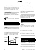
S
ensor placement:
Best efficiency is attained when the pressure
transmitter is placed at the farthest significant load
in the system. This setup allows measurement of
actual system peformance. If this is not practical,
the pressure transmitter is usually placed close
to the discharge of the pumps.
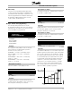
The default feedback process described for setup
in this chapter is used when a pressure feedback
signal is measured at the outlet of the pumps. The
cascade controller uses the feedback to estimate the
setpoint required at various rates of flow. Setpoint
1 is the minimum pressure required when the
system is running with only the AFD operating at full
speed. Setpoint 2 is the maximum pressure required
when the system is running with all pumps at full
capacity. A theoretical value calculates pressure
loss in the system under minimum and maximum
loads. The controller adjusts the loading based
upon the number of pumps in operation.
When the pressure transmitter is placed at the farthest
significant load in the system, common in HVAC
applications, see alternative ways of programming
the cascade controller described in Alternate
Programming at the end of this chapter.
Although pump applications are highlighted in this
chapter, the procedures and setting are nearly identical
for fan applications, such as controlling multiple cooling
tower fans. Differences between fan and pump
settings are described in the procedures.
General information on how to program the AFD
through the local control panel keypad are presented
in Chapter 4, User Interface.
MG.60.I5.22 - VLT is a registered Danfoss trademark
50