
Instruction manual


Cascade Controller Option
Description of choice:
Set the desired feedback maximum within the
programmed minimum and maximum in Quick Menu
items 014 and 015. The process unit is selected
in Quick menu item 013, Process Units. In a water
supply system with little leakage, the difference
between Setpoint 1 (set in Quick Menu item 028) and
Setpoint 2 is typically around 10% to 15%.
Quick Menu 031 Par. 721 De-stage timer
(DESTAGE TIME)
Value:
0 - 300 sec. (301= OFF)
✭ OFF
Function:
The de-stage timer starts when the adjustable speed
pump is running a minimum speed with one or more
constant speed pumps in operation and system
requirements satisfied. In this situation, the adjustable
speed pump contributes little to the system. When
the programmed value of the timer expires, a fixed
speed pump is destaged and the adjustable speed
pump accelerated to maintain system requirement.
This saves energy and avoids dead head water
circulation within the adjustable speed pump.
Description of choice:
Set the de-stage timer interval. When sleep mode is
activated, ensure the interval is set lower or equal to
the value of the sleep mode timer (parameter 403).
NOTE
Sleep mode activates when the adjustable speed
pump is the only pump running. To turn off the
destage timer, turn off sleep mode first. Set
parameter 403, Sleep Mode to 301 seconds (off), then
parameter 721, De-stage Time r to 301 seconds (off).
Quick Menu 032 Par. 722 Pump cycling
(PUMPCYCLING)
Value:
Enabled - Disabled
✭ Enabled
Function:
To achieve equal hours of operation in the constant
speed pumps, pump use can be cycled. Timers
on the relay outputs (relays 6, 7, 8, and 9) monitor
the running hours of each pump. In staging on, the
relay (pump) with the least hours is switched on. In
destaging, the relay (pump) with the most hours is
switched off. Not operating a pump over long time
periods can create corrosion concerns.
If cycling is disabled, the controller follows the fixed
pattern of relay activation (6, 7, 8 and 9) regardless of the
running hour counters. Destaging is in the reverse order.
Description of choice:
Choose whether to disable or enable the function.
Quick Menu 040 Par. 420 PID normal/inverse
control
(PID NOR/INV. CTRL)
Value:
✭Normal (NORMAL)
[0]
Inverse (INVERSE)
[1]
Function:
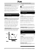
This determines how the drive’s PID controller
responds to a difference between the setpoint and
feedback. Normal is when the drive is to reduce the
output frequency as the feedback signal increases.
Inverse is when the drive is to increase the output
frequency as the feedback signal increases.
Description of choice:
Select the PID controller response option.
MG.60.I5.22 - VLT is a registered Danfoss trademark
46