
Instruction manual


Cascade Controller Option
Standard Cascade
Controller Setup
■ Standard Cascade Controller Setup
■ Introduction
In standard cascade control, an AFD with the
cascade option card controls a motor in response
to system feedback signals while staging additional
constant speed motors on and off. By varying
the speed of the initial motor, variable speed
control is provided for the system.
The motors can be of equal or differing sizes. The
controller offers a selection of eight pre-defined
pump combinations (see parameter 712).
A de-stage timer takes effect in standard control mode
when the drive runs continuously at minimum speed
with one or more constant speed motors running. The
de-stage timer is programmable to avoid frequent
staging on and off of the constant speed motors.
Although pump applications are highlighted in this
chapter, the procedures and settings are nearly
identical for other applications. The feedback process
setup described, assumes that a pressure feedbac
k
signal is measured at the outlet of the pumps.
P
rogramming instructions:
Instructions for programming Quick Menu items
1-20 are presented in Chapter 5, VLT Drive and
Cascade Controller Card Setup. Parameters
1-20 must be programmed before programming
Standard cascade control options.
The instructions in this chapter desc
ribe procedures for
programming the AFD for standard cascade control
mode operation. The Quick Menu simplifies setup
since the 44 parameters are pro
grammed in sequence.
Procedures for programming are in the following order:
Initial Setup: Quick Menu items 1-20
Step 1: Standard control mode programming
Step 2: Optimization of the process regulator
Alternate Programming
Optimizing the process regulator is performed after
system start up. The procedures are described
in Chapter 9, System
Optimization.
S
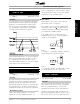
ensor placement:
Best efficiency is attained when the pressure
transmitter is placed at the farthest significant load
in the system. This setup allows measurement of
actual system peformance. If this is not practical,
the pressure transmitter is usually placed close
to the discharge of the pumps.
The cascade controller uses the feedback to estimate
the setpoint required at various rates of flow. Setpoint
1 is the minimum pressure required when the
system is running with only the AFD operating at full
speed. Setpoint 2 is the maximum pressure required
when the system is running with all pumps at full
capacity. A theoretical value calculates pressure
loss in the system under minimum and maximum
loads. The controller adjusts the loading based
upon the number of pumps in operation.
When the pressure transmitter is placed at the farthest
significant load in the system, common in HVAC
applications, see alternative ways of programming
the cascade controller described in Alternate
Programming at the end of this chapter.
General information on how to program the AFD
through the local control panel keypad are presented
in Chapter 4, User Interface.
■ Lead Pump Alternation
The programming of the lead pump alternation
function is basically done as for the standard cascade
controller. A few parameters have been added
and a few parameters have been changed. For
further information please see section Programming
of lead pump alternation function.
MG.60.I5.22 - VLT is a registered Danfoss trademark
39