
Instruction manual


Cascade Controller Option
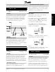
is a fault condition or when the drive looses power.
Terminal wires 1 and 3 are wired together.
Alarm is selected when a loss of power should not cause
an alarm indication. Wire terminals 1 and 2 together.
See the AFD Operating Instructions for a
detailed list of relay options.
Description of choice:
Select relay 1 function.
Quick Menu 012 Par. 326 Output relay 2
(RELAY 2 FUNCTION)
Value:
29 optional settings
✭ RUNNING
Function:
This output activates relay switch 02. This low voltage
relay is generally programmed to provide a remote
run indication. There are 29 optional settings.
Running makes this relay close when the drive is
running. This is the default setting.
Description of choice:
Select relay 2 function.
Quick Menu 013 Par. 415 Units relating
to closed loop
(REF. / FDBK. UNIT)
Value:
No unit
[0]
✭%
[1]
rpm
[2]
ppm
[3]
pulse/s
[4]
l/s
[5]
l/min
[6]
l/h
[7]
kg/s
[8]
kg/min
[9]
kg/h
[10]
m
3
/s
[11]
m
3
/min
[12]
m
3
/h
[13]
m/s
[14]
mbar
[15]
bar
[16]
Pa
[17]
kPa
[18]
mVS
[19]
kW
[20]
°C
[21]
GPM
[22]
gal/s
[23]
gal/min
[24]
gal/h
[25]
lb/s
[26]
lb/min
[27]
lb/h
[28]
CFM
[29]
ft
3
/s
[30]
ft
3
/min
[31]
ft
3
/h
[32]
ft/s
[33]
in wg
[34]
ft wg
[35]
PSI
[36]
lb/in
2
[37]
HP
[38]
°F
[39]
Function:
This unit will be used for the reading in the Display
mode and as a unit for Minimum / Maximum Feedback,
Minimum / Maximum Refe rence, Warning Feedback
High/Low and for the H1, H0 and the calculated
Hmx parameter settings/readings.
Description of choice:
Select the unit for the reference/feedback signal.
Quick Menu 014 Par. 413 Minimum feedback
(MIN. FEED BACK)
Value:
-999,999.999 - FB
MAX
✭ 0.000
Function:
Parameters 413, Minimum feedback and 414,
Maximum feedback are used to scale the feedback
signal ensuring that it shows the feedback signal
proportionally to the signal at the input.
MG.60.I5.22 - VLT is a registered Danfoss trademark
34