
Instruction manual


Cascade Controller Option
Quick Menu 009 Par. 206 Ramp-up time
(RAMP U P TIME)
Value:
1 - 3600 sec.
✭ Depends on unit
Function:
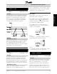
The ramp-up time is the acceleration time from 0 Hz
to the rated motor frequency (parameter 104, Motor
frequency). It is assumed that the output current
does not reach the current limit (set in parameter
215, Current limit). This determines the maximum
acceleration rate for all modes of operation.
Description of choice:
Set the desired ramp-up time. Too long of a ramp up
time can cause sluggish drive operation. Too short
ofarampuptimecancausethedrivetogointo
current limit during acceleration or cause unacceptable
torque pulses in the controlled system.
Quick Menu 010 Par. 207 Ramp-down time
(RAMP DOWN TIME)
Value:
1 - 3600 sec..
✭ Depends on unit
Function:
The ramp-down time is the deceleration time from
the rated motor frequency (parameter 104, Motor
frequency) to 0 Hz. This ramp-down time may be
automatically extended to prevent an overvoltage trip if
the load regenerates to the drive. This determines the
maximum deceleration rate for all modes of operation.
Description of choice:
Set the desired ramp-down time. Too long of a
ramp down can cause sluggish operation. Too
short of a ramp down can cause the drive to trip off
due to high DC bus voltage or cause unacceptable
torque pulses in the controlled system.
■ Relay outputs
Relay outputs 1 and 2 can be used to give the
present drive status or a warning.
Iftheoutputisusedasavoltageoutput(0-10V),
a pull-down resistor of 500
should be fitted to
terminal 39 (common for analogue/digital outputs.
See chapter 10 for additional detail).
If the output is used as a current output, the
resulting impedence of the connected equipment
should not exceed 500 W.
Relay 1
1 - 3 break, 1 - 2 make Max. 240 VAC, 2 Amp. The
relay is with the main and motor terminals.
Relay 2
4 - 5 make Max. 50 VAC, 1 A, 60 VA. Max. 75 VDC,
1 A, 30 W. The relay is on the control card.
Quick Menu 011 Par. 323 Output relay 1
(RELAY 1 FUNCTION)
Value:
29 optional settings
✭ NO ALARM
Function:
This output activates relay switch 01. This 240 volt,
Form C relay can be used for status and warnings.
There are 29 optional settings. It is generally
programmed to provide a remote alarm indication.
No Alarm is the default setting. This indicates the
drive is operating properly and the contact is closed.
The contact opens to indicate an alarm when there
MG.60.I5.22 - VLT is a registered Danfoss trademark
33
AFD and Cascade
Controller Setup