
Instruction manual


Cascade Controller Option
AFD and Cascade
Controller Setup
■ AFD and Cascade Controller Setup
■ Introduction
A new quick menu list is activated when a cascade
controller option card is installed in the AFD. The
original 12 items are expanded to 44 quick menu
items that allow programming additional drive
and cascade controller functions. See Chapter
4, Changed Drive Functions.
The first 20 items on the new quick menu must be
programmed in sequence for initial drive and cascade
controller setup. (See block diagram.) These 20 items
are common to both Standard cascade control mode
and Master/Slave control mode. After initial setup
is complete, additional quick menu items program
the drive for the selected mode of operation. Those
instructions are available in Chapter 7, Standard
Cascade Control Mode Setup and Chapter 8,
Master/ Slave Control Mode Setup.
Chapter 9, System Optimization, provides instructions
for final adjustments to reach maximum drive and
controller efficiency after system start up.
Items 2-6 are motor characteristics. In Standard
cascade control mode, only the motor data from
the
variable speed motor run by the cascade controller
are entered. In Master/Slave control, only data from
the motor controlled by the Master dri
ve are entered
at this time. Items 7-19 are basic cascade controller
settings used in either mode of operation. Item 20
selects the mode of operation for further setup.
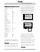
The Quick Menu Summary table on the next
page describes the menu items.
The AFD has four independent setups that can be
programmed. The initial programming in this chapter
is stored as Setup 1. See Alternative Programming
at the end of this chapter for instructions on using
the drive’s multi-setup capability.
AFDs delivered with the cascade controller option
card already installed, or prepared for field installation,
have been programmed with factory settings typical
for operation. These settings may be satisfactory
for initial start up of the system.
See Chapter 5, Use Interface, for instructions
on programming the AFD.
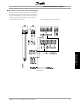
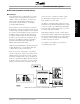
AFD and Cascade Controller Card Setup Block Diagram
MG.60.I5.22 - VLT is a registered Danfoss trademark
29