
Instruction manual


Cascade Controller Option
Data Item: Unit:
Resulting reference, % [%]
Resulting reference, unit [unit]
Frequency [Hz]
% of maximum output
frequency
[%]
Motor current [A]
Power [kW]
Power Power [HP]
Output energy [kWh]
Hours run [hours]
User-defined readout [unit]
Setpoint 1 [unit]
Setpoint 2 [unit]
Feedback 1 [unit]
Feedback 2 [unit]
Feedback [unit]
Motor voltage [V]
DC-link voltage [V]
Thermal load on motor [%]
Thermal load on VLT [%]
Input status, digital input [binary code]
Input status, analog
terminal 53
[V]
Input status, analog
terminal 54
[V]
Input status, analog
terminal 60
[mA]
Output status, relay status [binary code]
Pulse reference [Hz]
External reference [%]
Heat sink temperature [°C]
comm. option card
warning
[HEX]
LCP display text
Status word [HEX]
Control word [HEX]
Alarm word [HEX]
PID Output [Hz]
PID Output [%]
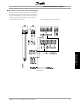
Three operating data values can be shown in the
first display line and one in the large display line,
programmed via parameters 007, 008, 009, and 010.
D
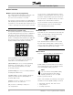
isplay mode I
´
In Display mode I, the drive is in Auto mode with
reference and control determined via the control
terminals. Below is an example in which the drive
is running in setup 1, in Auto mode, with a remote
reference, and at an output frequency of 40 Hz.
The text in line 1, FREQUENCY, describes the
meter shown in the large display. Line 2 (large
display) shows the current output frequency (40.0
Hz), direction of rotation (reverse arrow), and active
setup (1). Line 3 is blank. Line 4 is the status line
and the information is automatically generated for
display by the drive in response to its operation. It
shows that the drive is in auto mode, with a remote
reference, and that the motor is running.
175ZA683.10
SETUP
1
FREQUENCY
40.0Hz
AUTO REMOTE RUNNING
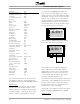
Status line (Line 4): Additional automatic displays
for the drive status line are shown below.
175ZA684.10
40.0Hz
80.0% 5.08A 2.15kW
SETUP
1
AUTO REMOTE RUNNING
HAND LOCAL STOP
OFF RAMPING
JOGGING
.
.
.
.
STAND BY
The left indicator on the status line displays the
active control mode of the VLT drive. AUTO is
displayed when control is via the control terminals.
HAND indicates that control is local via the keys
on the LCP. OFF indicates that the drive ignores
all control commands and will not run.
The center part of the status line indicates the reference
element that is active. REMOTE means that reference
from the control terminals is active, while LOCAL
indicates that the reference is determined via the
[+] and [-] keys on the control panel.
The last part of line 4 indicates the drive’s operational
status, for example: RUNNING, STOP, or ALARM.
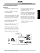
D
isplay mode II
MG.60.I5.22 - VLT is a registered Danfoss trademark
26