
Instruction manual


Cascade Controller Option
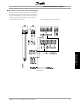
■ Master drive in master/slave control wiring diagram
The wiring diagram below shows an example of a
Master drive in Master/Slave cascade control. The
system demonstrates a 4-20 mA pressure transmitter,
an external safety interlock and four slave drives. The
slave drive speed reference is provided from terminal
17 as a pulse signal. The relays on the option card are
used for the Start/Stop command to the slave drives.
Power terminal connections Control board terminal connections Option card terminal connections
Master Drive
NOTE
Terminal 16 or 17 must be connected to
terminal 12 or 13 and must be programmed
to "System start".
MG.60.I5.22 - VLT is a registered Danfoss trademark
20