
Instruction manual


Cascade Controller Option
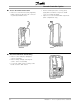
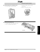
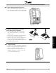
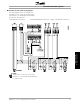
■ Lead Pump Alternation Wiring Diagram
Every pump must be fitted with a double power
contactor with a safety mechanical interlock. The wiring
of the system is shown in the diagrams below.
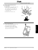
• Relays R6, R7, R8, and R9 are the Cascade
Controller card relays
• When all relays are idle (OFF) the first relay ON
sets the power switch corresponding to the pump
controlled by the frequency converter. For example
R6 set V1, i.e. P1 becomes the lead pump.
• V1 block F1 in off position though the
mechanical interlock
• Auxiliaries NC contacts of V1 prevent V2,
V3 and V4 activation
• The first fixed speed pump is P2 (through F2) by
relay R7, then P3 (F3) by R8 and so on.
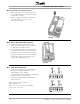
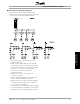
• When the timer reaches its preset value all pumps
are switched off in the same order as switched
on i.e. P4, P3, P2 and then P1
• The system restarts with R7 relay on which set pump
P2 as the lead pump controlled by the VLT, then R8,
R9, R6 (P3, P4, P1 running fixed speed on mains)
MG.60.I5.22 - VLT is a registered Danfoss trademark
19
Installation and
Wiring Instructions