
Instruction manual
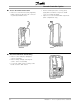

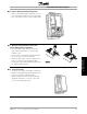


Cascade Controller Option
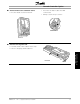
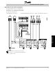
■ Standard casc ade control wiring diagram
The wiring diagram shows an example for a
standard cascade control system with 4 fixed
speed motors, a 4-20 mA pressure transmitter,
and external safety interlock.
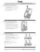
Power terminal connections Control board terminal connections Option card terminal connections
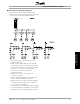
NOTE
Terminal 16 or 17 must be connected to
terminal 12 or 13 and must be programmed
to "System start".
MG.60.I5.22 - VLT is a registered Danfoss trademark
17
Installation and
Wiring Instructions