
Instruction manual


Cascade Controller Option
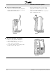
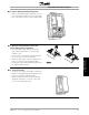
■ 9. Install Chassis Ground Connections
• Align ground strips over corresponding screw
holes. (Strip with fewest contact points mounts
on right side of chassis.)
• Replace screws removed and add additional
screws provided, as necessary. Use a
Torx T-20 screw driver.
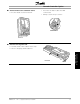
■ 10. Replace AFD Control Board Cassette
• Attach LCP keypad craddle to AFD control
board cassette removed in step 4. Ensure not
to crimp option card ribbon cables.
• Connect two ribbon cables to control board in
corresonding connectors as removed in step
3.
• Hinge AFD cassette at top of AFD chassis and
reposition into place. Use Torx T-20 screwdriver
to fasten two captive screws. Ensure not to
crimp control board ribbon cables.
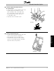
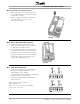
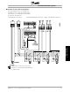
■ 11. Relay Output Connection
• Connect relay output cables to terminal blocks
provided as required by application. (See
wiring diagrams in this chapter.)
• Insert relay terminal blocks firmly into corresponding
terminal sockets on control board.
• Secure relay wiring with bottom right wiring
clamp and fasten.
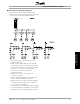
Relay 6-9: A-B make, A-C break
Max. 240 VAC, 2 A
Max. cross-section: 1.5 mm
2
(28-16 AWG)
Torque: 0.22 - 0.25 Nm
MG.60.I5.22 - VLT is a registered Danfoss trademark
14