Instruction Manual Cascade Controller Option VLT® 6000 HVAC VLT® 8000 AQUA
Cascade Controller Option ■ Contents Safety and precautions 3 4 4 Operation modes 6 6 7 7 8 ................................................................................ Safety regulations ................................................................................................... Warning against unintended start ........................................................................... ............................................................................................
Cascade Controller Option Initial Setup ............................................................................................................ 40 Alternate programming ........................................................................................... 49 Master/Slave Cascade Control Setup 50 50 50 51 55 55 System Optimization 57 57 57 58 Feedback Transmitter Wiring 59 59 59 59 60 60 61 ................................................... Introduction .....................................
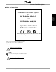
Cascade Controller Option and precautions Cascade Controller Option for 175ZA677.12 ■ Safety Safety and precautions VLT 6000 HVAC and VLT 8000 AQUA Operating Instructions Software version: 2.x These Operating Instructions can be used with all cascade controller options with software version 2.x. The software version can be seen from parameter 624. When reading through this Operating Instructions, you will come across various symbols that require special attention.
Cascade Controller Option The voltage of the AFD is dangerous whenever the equipment is connected to mains. Incorrect installation of the motor or the frequency converter may cause damage to the equipment, serious personal injury or death. Consequently, the instructions in this manual, as well as national and local rules and safety regulations, must be complied with.
Cascade Controller Option MG.60.I5.22 - VLT is a registered Danfoss trademark 5 Safety and precautions Touching the electrical parts may be fatal - even after the equipment has been disconnected from mains.
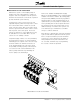
Cascade Controller Option ■ Operation modes ■ Cascade Control Operation With the cascade controller option card, the AFD (Adjustable Frequency Drive) can automatically control up to five motors. Staging motors on or off is done cyclically, in accordance with operating hours. This function assures equal use over time and eliminates concern about starting a seldom used motor.
Cascade Controller Option The motors can be of equal or differing sizes. The controller offers a selection of eight pre-defined pump combinations. Selections allow mixing pumps of 100%, 200% and 300% capacity. This provides a dynamic capacity range of 9 to 1. The AFDs internal PID controller directs the cascade option card based upon the feedback signal. The cascade controller will continue operation of the constant speed motors to meet demand should the drive trip.
Cascade Controller Option ■ Master/Slave Cascade Control Mode Master/slave systems control multiple pumps in parallel at the same output frequency. Pumps are staged on and off as required to meet the system’s demand. The master/slave control mode of operation provides maximum system efficiency. In master/slave control, each motor has its own adjustable frequency drive which responds to control from a master drive which contains the cascade option card.
Cascade Controller Option ■ Installation and Wiring Instructions ■ Installing the Cascade Controller Option Card This chapter provides instructions for installing the cascade controller option card into an AFD. In Standard cascade control mode, the option card installs into the AFD controlling up to four additional motors. In Master/Slave mode, the option card installs in the Master drive controlling up to four additional slave drives.
Cascade Controller Option ■ 1. Access to Control Card Cassette • Remove Local Control Panel (LCP) keypad by pulling out from top by hand. LCP connector on panel back will disconnect. • • Remove terminal protective cover by gently prying with screw driver at top notch and lift cover out of guide pin fittings. Open access cover to internal AFD components. (Drive configurations vary.) ■ 2. Disconnect AFD Drive Control Wiring • Remove control wiring by unplugging connector terminals.
Cascade Controller Option ■ 3. Remove AFD Cassette and Ribbon Cables • Lift control board cassette from bottom. • • Disconnect two ribbon cables from AFD control board. Unhinge cassette at top to remove. Installation and Wiring Instructions Installation and Wiring Instructions ■ 4. Remove LCP Keypad Cradle • Push tabs at side of LCP cradle to release clips. • Pull out to disengage and lift cradle free. MG.60.I5.
Cascade Controller Option ■ 5. Cascade Option Card Ribbon Cable Routing • Route ribbon cables from cascade controller option card through slot at side of AFD control board cassette. Option card mounts with component side down. • Feed plastic option card insulation pad through terminal opening in control board cassette. • Insert edge of option card into slot (A) in side of cassette. • Align opposite side of card with mounting holes (B) provided. ■ 6.
Cascade Controller Option ■ 7. Connect Option Card Ribbon Cable to VLT Control Board • Pull up collar (A) of control board ribbon cable socket. • DO NOT remove blue insulation on end of option card ribbon cable. Insert ribbon cable into corresponding socket (B) on AFD control board and push collar closed. Be sure not to crimp ribbon cables. • Repeat procedure for all ribbon cables. MG.60.I5.22 - VLT is a registered Danfoss trademark Installation and Wiring Instructions ■ 8.
Cascade Controller Option ■ 9. Install Chassis Ground Connections • Align ground strips over corresponding screw holes. (Strip with fewest contact points mounts on right side of chassis.) • Replace screws removed and add additional screws provided, as necessary. Use a Torx T-20 screw driver. ■ 10. Replace AFD Control Board Cassette • Attach LCP keypad craddle to AFD control board cassette removed in step 4. Ensure not to crimp option card ribbon cables.
Cascade Controller Option ■ 12. Remove Wiring Clamp Mounting Fixture • Option card insulation pad is designed to use top most cable wiring clamp screw hole for attaching. • Use screw driver to remove top most wiring clamp. Installation and Wiring Instructions ■ 13. Reconnect AFD Control Terminals and Secure Option Card InsulationPad • Reconnect AFD control terminals removed in step 2 by pressing firmly into corresponding terminal socket.
Cascade Controller Option ■ Transmitter wiring Please refer to chapter 10, Feedback Transmitter Wiring. 16 MG.60.I5.
Cascade Controller Option ■ Standard cascade control wiring diagram The wiring diagram shows an example for a standard cascade control system with 4 fixed speed motors, a 4-20 mA pressure transmitter, and external safety interlock. Control board terminal connections Option card terminal connections Installation and Wiring Instructions Power terminal connections NOTE Terminal 16 or 17 must be connected to terminal 12 or 13 and must be programmed to "System start". MG.60.I5.
Cascade Controller Option ■ Optional Hand/Off/Auto Switch Optional Hand/Off/Auto Switch In standard cascade control mode, an optional Hand/Off/Auto switch on the constant speed motor starter is common. During normal operation, the switch is set to AUTO and the drive will signal automatic start and stop commands to the motor. The HAND position allows manual operation of the motor. The motor can be disabled by setting the switch to OFF.
Cascade Controller Option • • • • • • • Installation and Wiring Instructions ■ Lead Pump Alternation Wiring Diagram Every pump must be fitted with a double power contactor with a safety mechanical interlock. The wiring of the system is shown in the diagrams below. Relays R6, R7, R8, and R9 are the Cascade Controller card relays When all relays are idle (OFF) the first relay ON sets the power switch corresponding to the pump controlled by the frequency converter. For example R6 set V1, i.e.
Cascade Controller Option ■ Master drive in master/slave control wiring diagram The wiring diagram below shows an example of a Master drive in Master/Slave cascade control. The system demonstrates a 4-20 mA pressure transmitter, Power terminal connections an external safety interlock and four slave drives. The slave drive speed reference is provided from terminal 17 as a pulse signal. The relays on the option card are used for the Start/Stop command to the slave drives.
Cascade Controller Option ■ Slave drive in master/slave control wiring diagram Each slave drive is wired in the same way, receiving the Start/Stop command and a pulse speed reference from the master drive. The speed reference and its common are typically looped from Slave-to-Slave. Control board terminal connections Installation and Wiring Instructions Power terminal connections Slave Drive MG.60.I5.
Cascade Controller Option ■ Changed Drive functions ■ Introduction Installation of the Cascade Controller Option card into the AFD overrides some existing drive functions. Changes to the default parameter setting are shown in the tables below. Data entered into the drive parameters are used to program the drive and cascade controller for system operation. The modified parameter default settings make programming the cascade controller easier.
Cascade Controller Option Do not use these functions as emergency stops. Some functions do not turn off all pumps. Standard cascade control mode Stop functions in Standard cascade control are described in the table below. In a sequenced stop, there is a one ramp-down time delay between each staging off of motors. Standard Cascade Control Function Description OFF/STOP key Controller decelerates its motor to a stop. Provides a sequenced stop for all constant speed motors in opposite order as staged on.
Cascade Controller Option ■ User Interface ■ How to use the LCP for programming The combined display and keypad on the front of the AFD is called the Local Control Panel (LCP). The LCP is the user interface to the AFD. The LCP has several user functions: programming the AFD; displaying operational data, along with warnings and cautions; to reset the drive after a fault; and, in local control, to start/stop and control the speed of the drive.
Cascade Controller Option • • • • • • Reversing Setup select lsb - Setup select msb Jog Run permissive Lock for data change Stop command from serial communication [OFF/STOP] is used for stopping the connected motor in Hand or Auto mode. This key can be diabled in parameter 013. If the stop function is activated, the main display will flash. [AUTO START] is used if the AFD is to be controlled through the control terminals.
Cascade Controller Option [A] [kW] Power [HP] [kWh] [hours] [unit] [unit] [unit] [unit] [unit] [unit] [V] [V] [%] [%] [binary code] [V] FREQUENCY 40.0Hz [mA] [binary code] [Hz] [%] [°C] [HEX] [HEX] [HEX] [HEX] [Hz] [%] Display mode I ´ In Display mode I, the drive is in Auto mode with reference and control determined via the control terminals. Below is an example in which the drive is running in setup 1, in Auto mode, with a remote reference, and at an output frequency of 40 Hz.
Cascade Controller Option 1 AUTO REMOTE RUNNING REF% CURR.A.POW.,KW 60.0Hz SETUP 1 175ZA686.10 Display mode III Press and hold the [DISPLAY MODE] key while in Mode II. Mode III is visible as long as the key is depressed. The top line changes to identify the data names and units displayed. Lines 2 and 4 are unchanged. When the key is released, the display returns to Mode II. AUTO REMOTE RUNNING USE +/- 40Hz 40.0Hz 175ZA688.
Cascade Controller Option ■ Parameter setting procedure Enter or change parameter data or settings as follows: 1. Press [Quick Menu] or [Extended Menu] key. 2. Use [+] and [-] keys to find parameter you choose to edit. 3. Press [Change Data] key. 4. Use [+] and [-] keys to select correct parameter setting. To move to a different digit within a numeric parameter, use < and > arrows. Flashing cursor indicates digit selected to change. 5.
Cascade Controller Option and Cascade Controller Setup ■ Introduction A new quick menu list is activated when a cascade controller option card is installed in the AFD. The original 12 items are expanded to 44 quick menu items that allow programming additional drive and cascade controller functions. See Chapter 4, Changed Drive Functions. The first 20 items on the new quick menu must be programmed in sequence for initial drive and cascade controller setup. (See block diagram.
Cascade Controller Option ■ Quick Menu Summary Quick Menu Parame- number ter num- Name Units ber Basic Drive Set Up parameters 001 001 Language Range Factory setting 10 languages See Instruction Manual for your AFD model.
■ Language Quick Menu 001 Par. 001 Language 75 HP (55.00 KW) 100 HP (75.00 KW) 125 HP (90.00 KW) 150 HP (110.00 KW) 200 HP (132.00 KW) 250 HP (160.00 KW) 300 HP (200.00 KW) 350 HP (250.00 KW) 400 HP (300.00 KW) 450 HP (315.00 KW) 500 HP (355.00 KW) 600 HP (400.00 KW) ✭Depends on the unit (LANGUAGE) Value: ✭English (ENGLISH) German (DEUTSCH) French (FRANCAIS) Danish (DANSK) Spanish (ESPAÑOL) Italian (ITALIANO) Swedish (SVENSKA) Dutch (NEDERLANDS) Portuguese (PORTUGUESA) Finnish (SUOMI) [055.00] [075.
Cascade Controller Option Description of choice: Select a value that equals the nameplate data on the motor, regardless of the AC input voltage of the AFD. NOTE It is important to set the correct value, since this forms part of the VVC+ control feature. The maximum value equals frequency x 60. Frequency is set in parameter 104, Motor frequency. Quick Menu 004 Par. 104 Motor frequency (MOTOR FREQUENCY) Value: 50 Hz 60 Hz ✭ 60 Function: This is where the rated motor frequency is selected.
Cascade Controller Option Quick Menu 009 Par. 206 Ramp-up time (RAMP UP TIME) ✭ Depends on unit Function: The ramp-up time is the acceleration time from 0 Hz to the rated motor frequency (parameter 104, Motor frequency). It is assumed that the output current does not reach the current limit (set in parameter 215, Current limit). This determines the maximum acceleration rate for all modes of operation. ■ Relay outputs Relay outputs 1 and 2 can be used to give the present drive status or a warning.
Cascade Controller Option is a fault condition or when the drive looses power. Terminal wires 1 and 3 are wired together. Alarm is selected when a loss of power should not cause an alarm indication. Wire terminals 1 and 2 together. See the AFD Operating Instructions for a detailed list of relay options. Description of choice: Select relay 1 function. Quick Menu 012 Par. 326 Output relay 2 (RELAY 2 FUNCTION) Value: 29 optional settings ✭ RUNNING Function: This output activates relay switch 02.
Cascade Controller Option Quick Menu 017 Par. 228 Warning High feedback Set the value to be shown on the display when the feedback signal is at its minimum value. Quick Menu 015 Par. 414 Maximum feedback (MAX. FEEDBACK) Value: FBMIN - 999,999.999 ✭ 100.000 Function: Parameters 413, Minimum feedback and 414, Maximum feedback are used to scale the feedback signal ensuring that it shows the feedback signal proportionally to the signal at the input.
Cascade Controller Option Quick Menu 019 Par. 205 Maximum reference (MAX. REFERENCE) Value: Par. 204 RefMIN - par. 414 Maximum feedback ✭ 50.000 Hz Function: The Maximum reference gives the maximum value that can be assumed by the sum of all references. The Maximum Reference is limited to be with the settings of Parameter 414 Maximum Feedback. The Maximum reference is ignored when the local reference is active (parameter 203 Reference site).
Cascade Controller Option ■ Alternate programming Setup configuration and copying parameters The AFD has four parameter setups that can be programmed. Each setup acts independently in controlling the drive. An example application would be programming different setups for day/night or summer/winter operation. Any of the four setups can be used. Description of choice: The setup is selected in Extended Menu parameter 002, Active Setup, for programming and operation.
Cascade Controller Option Extended Menu Par. 004 LCP Copy (LCP COPY) Value: ✭No copying (NO COPY) Upload all parameters (UPLOAD ALL PARAMET.) Download all parameters (DOWNLOAD ALL PARAM.) Download power-independent parameters (DOWNLOAD SIZE INDEP.) [0] [1] [2] [3] Function: This parameter is used to copy all parameter setups to or from the Local Control Panel (LCP) keypad. It can be used to store a backup copy of all parameters in the LCP or to copy all setups from one drive to another.
Cascade Controller Option Cascade Controller Setup ■ Introduction In standard cascade control, an AFD with the cascade option card controls a motor in response to system feedback signals while staging additional constant speed motors on and off. By varying the speed of the initial motor, variable speed control is provided for the system. The motors can be of equal or differing sizes. The controller offers a selection of eight pre-defined pump combinations (see parameter 712).
Cascade Controller Option ■ Initial Setup Instructions for programming Quick Menu items 1-20 are presented in Chapter 5, AFD and Cascade Controller Card Setup . Parameters 1-20 must be programmed before programming additional options described below. Description of choice: Select the pump combination and capacities from the choices offered. Quick Menu 021 Par.
Cascade Controller Option Quick Menu 022 Par. 713 Staging Bandwidth % (STAGING BANDW%) Value: 1 - 100% programmed. If the pressure decreases to within the SBW before the timer has elapsed, the timer is reset. ✭ 10% Function: In cascade control systems, to avoid frequent switching of fixed speed pumps, the desired system pressure is typically kept within a bandwidth rather than at a constant level. The staging bandwidth (SBW) is programmed as a percentage of the setpoint (desired pressure).
Cascade Controller Option Description of choice: Set the staging on time delay. A delay time of 30 seconds (factory setting) is sufficient in most systems. When encountering frequent staging, decease delay time. with increased familiarity with the system. See parameter 717, Override Bandwidth Timer. Quick Menu 025 Par.
Cascade Controller Option Quick Menu 027 Par. 718 Staging frequency Quick Menu 026 Par. 717 Override Bandw. timer (OVERRIDE TIMER) Value: 0 - 300 sec. ✭ 10 sec. Function: Staging a fixed speed pump creates a momentary pressure peak in the system, which might exceed the override bandwidth (OBW). It is not desirable to destage a pump in response to a staging pressure peak.
Cascade Controller Option system. Ensure that the staging frequency setting allows the check valve to remain open. Quick Menu 028 Par. 741 Destaging frequency (STD DESTAGE FRQ) Value: 0 - 100 % Fmax ✭ 10% Function: The lead pump (pump 1 in the figure) typically runs at minimum speed when destaging occurs. Turning off a fixed speed pump (pump X in the figure) creates a momentary pressure drop until the lead pump decelerates.
Cascade Controller Option (SETPOINT 1) Value: Feedback Min. to Feedback Max ✭ 0.000 Function: The default feedback process is used when a pressure feedback signal is measured at the outlet of the pumps. The cascade controller uses the feedback to estimate the setpoint required at various rates of flow. All other reference signals are ignored. Setpoint 1 is the minimum pressure required when the system is running with only the AFD operating at full speed.
Cascade Controller Option Description of choice: Set the desired feedback maximum within the programmed minimum and maximum in Quick Menu items 014 and 015. The process unit is selected in Quick menu item 013, Process Units. In a water supply system with little leakage, the difference between Setpoint 1 (set in Quick Menu item 028) and Setpoint 2 is typically around 10% to 15%. NOTE Sleep mode activates when the adjustable speed pump is the only pump running.
Cascade Controller Option ■ Programming of the Lead Pump Alternation Function The standard cascade controller parameters and the following parameters 750 - 753 are to be programmed. Select "Standard" in quick menu 020, par. 723 Operational mode select. • • • [0] Disabled (DISABLE) [1] Enabled - Standard mode (ENABLE) [2] Enabled - Indexed alternation (ENABLE INDEXED) where you choose [2].
Cascade Controller Option Description of choice: Select which pump you want to be the lead pump. Quick Menu 039 Par. 753 Alternation Restart Delay (ALT. RESTART DEL) Value: 0-60 ✭ 5 sec. Function: The controller makes sure, that a "new" lead pump is not started up before the "old" lead pump is stopped. The time in this parameter sets the delay from when the "old" lead pump is completely stopped until the "new" one must be started up. Description of choice: Set the desired time.
Cascade Controller Option The most common setup for feedback response is with a single transmitter located at the farthest significant load in the system. Programming the cascade controller option in this manner is described below. It is also possible for the PID to accept two feedback signals, making two-zone regulation available. For two feedback control, and for additional setting options, see the Operating Instructions for your AFD series.
Cascade Controller Option ■ Master/Slave Cascade Control Setup ■ Introduction In Master/Slave cascade control operation, the AFD with the cascade control option card is the Master. The Master drive controls the speed and staging on or off of up to four additional adjustable speed drives. The Master drive exports a pulse signal or analog speed signal through its output relays to the slave drives. It is recommended that a pulse signal be used for minimum electrical noise and for precise drive control.
Cascade Controller Option ■ Initial Setup Instructions for programming Quick Menu items 1-20 are presented in Chapter 5, AFD Drive and Cascade Controller Card Setup. Parameters 1-20 must be programmed into the Master drive before programming additional Master/Slave cascade control options described below. Description of choice: Set staging off delay time. In Master/Slave operation, 3 seconds is a typical value. Quick Menu 024 Par.
Cascade Controller Option The range is determined by Quick Menu item 14 (parameter 413, Minimum Feedback) and Quick Menu item 15 (parameter 414, Maximum Feedback). When the pressure feedback signal originates at the far end of the system, the drive does not need to compensate for system pressure changes due to flow. For this system configuration, or for two setpoint PID control, see Alternative Programming at the end of this chapter.
Cascade Controller Option Description of choice: Set the output of terminal 42 to Output Frequency (pulse sequence), (OUT.FREQ.PULSE) for Master/Slave operation as shown in the wiring diagram in Chapter 4. Using frequency pulse is a reliable way of providing the same speed reference to all slave drives. Current output is limited to two slave drives. System pressure and flow requirements can often be generated using parallel pumps at different efficiencies.
Cascade Controller Option Description of choice: Select the PID controller response option. 54 MG.60.I5.
Cascade Controller Option ■ Step 2: Slave Drive Programming The slave drives run in open loop mode and recieve stop/start and speed reference commands from the Master drive. Each slave drive must be programmed with the nameplate data from the motor it controls. All other applicable parameter settings must match the settings in the Master drive. All parameter settings can be transferred from one AFD drive to another by using the removeable keypad. Parameter 004, LCP Copy, allows this function.
Cascade Controller Option the drive’s PID controller to respond to system changes as programmed. Pumps or fans are staged on and off in response to the system feedback signal. The most common setup for feedback response is with a single transmitter located at the farthest significant load in the system. Programming the cascade controller option in this manner is described below. It is also possible for the PID to accept two feedback signals, making two-zone regulation available.
Cascade Controller Option ■ System Optimization ■ System start up and final adjustments After Master drive and slave programming is complete, and after all system safety procedures have been ensured and the system is operational, final adjustments can be made to reach maximum efficiency for drive and cascade controller operation. Final adjustments involves the following: a. Setting the best efficiency frequency in the cascade controller for staging and destaging pumps and fans b.
Cascade Controller Option ■ Optimization of the process regulator Quick Menu 043 Par. 423 PID proportional gain (PID PROP. GAIN) Value: 0.00 - 10.00 ✭ 0.30 time until the feedback signal stabilizes. Now increase the integration time from 15% to 50%. Starting and stopping the drive will produce the necessary error signal in the process to set the PID.
Cascade Controller Option ■ Feedback Transmitter Wiring ■ Connecting feedback transmitters Terminal 12 and 13 of the AFD provide access to a 24 VDC, 200 mA power supply. This can be used to power remote transmitters, so an external power supply is generally not needed. The diagrams below show how to wire two- and three-wire transmitters.
Cascade Controller Option Programming: Programming: Parameter Parameter Parameter Number Description Value 415 Ref./FDBK UNIT Process unit 413 MIN. FEEDBACK Transmitter low limit 414 MAX. FEEDBACK Transmitter high limit 417 2 FEEDBACK CALC. Desired operation 308 AI [V] 53 FUNCT. FEEDBACK 309 AI 53 SCALE LOW 0V 310 AI 53 SCALE HIGH 10V 311 AI [V] 54 FUNCT. FEEDBACK 312 AI 54 SCALE LOW 0V 313 AI 54 SCALE HIGH 10V 314 AI [mA] 60 FUNCT.
Cascade Controller Option Maximum is selected, the feedbacks will be equal to or less than their associated setpoints. Feedback 1 is associated with Setpoint 1 and Feedback 2 is associated with Setpoint 2. The two independent groupings are continuously monitored to satisfy both zones requirements. Transmitter connection to the AFD: The transmitters are connected to the AFD in the same way as shown above with 1 setpoint and 2 feedbacks.
Cascade Controller Option ■ Parameter group 700 definitions Para Name Description Unit Range Factory Change Setting During Data Type Conversion Index Operation 712 713 PUMP COMBINA- Selects number and size of TION slave pumps STAGING BANDW. % Pump Staging Bandwidth in No. 1-8 R6@100 No 5 0 % 1.0 - 100.0 5.0% Yes 6 -1 % of setpoint 714 DESTAGING DELAY Pump Staging Bandwidth off Sec. 0.0 - 3000.0 10 sec. Yes 6 -1 715 STAGING DELAY Pump Staging Bandwidth on Sec. 0.
Cascade Controller Option Conversion Index Factors Conversion Factor 3.6 100.0 10.0 1.0 0.1 0.01 0.001 0.0001 Parameter group 700, all parameters Conversion Index 74 2 1 0 -1 -2 -3 -4 DataType Descriptions Data type 3 4 5 6 7 9 Description Integer 16 Integer 32 Unsigned 8 Unsigned 16 Unsigned 32 Text string MG.60.I5.
Cascade Controller Option ■ Service parameters ■ Display information Parameters 724 through 738 provide operational information including the number of hours run, cycles, and the state of the relay for each pump. Par. 724 - 727 Pump-on time (PUMP x ON TIME) Parameter number Pump number 724 Pump 2 725 Pump 3 726 Pump 4 727 Pump 5 Value: h 0 - 130000 Function: The relay timer accumulates the hours (h) the pump has run (the relay switched on).
Cascade Controller Option ■ Relay status The display panel on the AFD allows reading the status of the relays. Press the [DISPLAY MODE] key. Use the [+] and [-] keys to scroll through the list to RELAY STATUS. The relay status readout consists of 8 binary digits. The first digit (starting from left) indicates the status of Relay 01 which is located in the power section of the AFD. The second digit is Relay 02 which is located on the AFD control card.
Cascade Controller Option ■ Index L Lead Pump Alternation ................................................... 39 66 MG.60.I5.
www.danfoss.com/drives 175R0240 MG60I522 *MG60I522* Rev.