
Operating instructions


VLT
®
5000 FLUX
Programming
Switching to ramp 2 may be activated via a signal
on digital input terminal 16, 17, 29, 32 or 33.
Ramp 1 will then be disabled.
210 Ramp-down time 2
(RAMPDOWNTIME2)
Value:
0.00 - 3600 sec. (closed loop)
0.05 - 3600 sec. (open loop)
✭ depends on unit
Function:
See description of parameter 208. Please note, that
the value 0.00 corresponds to 0.01 during speed.
Description of choice:
Set the desired ramp-down time.
Switching to ramp 2 is effected via a signal
on digital input terminal 16, 17, 29, 32 or 33.
Ramp 1 will then be disabled.
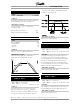
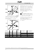
211 Jog ramp time (JOG RAMP TIME)
Value:
0.00 - 3600 sec. (closed loop)
0.05 - 3600 sec. (open loop)
✭ depends on unit
Function:
The jog ramp time is the acceleration/deceleration
time from 0 rpm to the rated motor frequency n
M,N
(parameter 104). It is assumed that the output current
is not higher than the torque limit (set in parameter 221).
The jog ramp time starts when a jog signal is
given via the control panel, the digital in
puts or
the serial communication port.
Description of choice:
Set the desired ramp time.
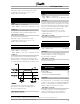
212 Quick stop ramp-down time
(Q STOP RAMP TIME)
Value:
0.00 - 3600 sec. (closed loop)
0.05 - 3600 sec. (open loop)
✭ depends on unit
Function:
The ramp-down time is the deceleration time from the
rated motor speed to 0 rpm, provided no over- voltage
arises in the inverter because of generating operation of
the motor or if the generated current becomes higher
than the torque limit (set in Parameter 222).
Quick-stop is activated by means of a signal
on digital input terminal 27 [2], or via the serial
communication port.
Description of choice:
Program the desired ramp-down time.
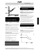
213 Jog speed
(JOG SPEED)
Value:
0.0 - Parameter 202
✭ 200 rpm
Function:
The jog speed n
JOG
is a fixed output speed at
which the frequency converter is running when
the jog function is activated.
Description of choice:
Set the desired frequency.
214 Reference function
(REF FUNCTION)
Value:
✭Sum. (SUM)
[0]
Relative (RELATIVE)
[1]
External/preset (EXTERNAL/PRESET)
[2]
Function:
To define how the preset references are to be added to
the other references. For this purpose, Sum or Relative
is used. It is also possible - by using the External/preset
function - to select whether a shift between external
references and preset references is desired.
Description of choice:
If Sum [0] is selected, one of the adjusted preset
references (parameters 215-218) is added as a
percentage of the maximum possible reference.
✭
= factory setting. () = display text [] = value for use in communication via serial communication port
MG.55.A7.02 - VLT is a registered Danfoss trademark
83