
Operating instructions

VLT
®
5000 FLUX
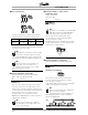
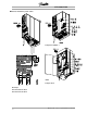
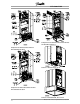
■ Electrical installation - external fan supply
Torque 0,5-0,6 Nm
Screwsize: M3
Available in 5122-5502, 380-500 V; 5032-5052,
200-240 V in all enclosure types.
Only for IP54 units in the power range VLT 5016-5102,
380-500 V and VLT 5008-5027, 200-240 V AC. If
the drive is supplied by the DC bus (loadsharing), the
internal fans are not supplied with AC power. In this
case they must be supplied with an external AC supply.
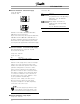
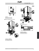
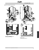
■ Electrical installation - 24 Volt external DC supply
(Only extended versions. Typecode: PS, PB,
PD,PF,DE,DX,EB,EX).
Torque: 0.5 - 0.6 Nm
Screw size: M3
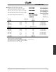
No. Function
35, 36
24 V external DC supply
External 24 V DC supply can be used as low-voltage
supply to the control card and any option cards
installed. This enables full operation of the LCP (incl.
parameter setting) without connection to mains.
Please note that a warning of low voltage will be
given when 24 V DC has been connected; however,
there will be no tripping. If 24 V external DC supply
is connected or switched on at the same time as
the mains supply, a time of min. 200 msec. must
be set in parameter 120 Start delay.
A pre-fuse of min. 6 Amp, slow-blow, can be
fitted to protect the external 24 V DC supply.
The power consumption is 15-50 W, depending
on the load on the control card.
NB!:
Use24VDCsupplyoftypePELVtoensure
correct galvanic isolation (type PELV) on the
control terminals of the frequency converter.
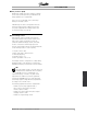
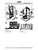
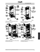
■ Electrical installation - relay outputs
Torque: 0.5 - 0.6 Nm
Screw size: M3
No. Function
1-3
Relay output, 1+3 break, 1+2 make
See parameter 323 of the Operating
Instructions. See also General
technical d ata.
4, 5
Relay output, 4+5 make See
parameter 326 of the Operating
Instructions.
See also Gene ral technical data.
MG.55.A7.02 - VLT is a registered Danfoss trademark
22