
Technical data

135 U/f-ratio
(U/f RATIO)
Value:
0.00 - 20.00 at Hz
Depends on unit
Function:
This parameter enables a shift in the ratio between
output voltage (U) and output frequency (f) linearly, so
as to ensure correct energizing of the motor and thus
optimum dynamics, accuracy and efficiency. The U/f-
ratio only affects the voltage characteristic if a selec-
tion has been made of Constant torque [1] parameter
101 Torque characteristic.
Description of choice:
The U/f-ratio is only to be changed if it is not possible
to set the correct motor data in parameter 102-109.
The value programmed in the factory settings is based
on idle operation.
136 Slip compensation
(SLIP COMP.)
Value:
-500 - +500% of rated slip compensation
100%
Function:
Slip compensation is calculated automatically, on the
basis of such data as the rated motor speed n
M,N
. In
this parameter, the slip compensation can be fine-
tuned, thereby compensating for tolerances on the
value for n
M,N
. Slip compensation is only active if a
selection has been made of Speedregulation, open
loop [0] in parameter 100 Configuration and Constant
torque [1] in parameter 101 Torque characteristic.
Description of choice:
Key in a % value.
137 DC hold voltage
(DC HOLD VOLTAGE)
Value:
0 - 100% of max. DC hold voltage
0%
Function:
This parameter is used to keep the motor (holding tor-
que) at start/stop.
Description of choice:
This parameter can only be used if a selection has
been made of DC hold in parameter 121 Start func-
tion or 122 Function at stop . To be set as a percentage
value of the max. DC hold voltage, which depends on
the choice of motor.
138 Brake cut out value
(Brake cut out)
Value:
0.5 - 132.0/1000.0 Hz
3.0 Hz
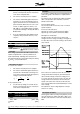
Function:
Here you can select the frequency at which the exter-
nal brake is released, via the output defined in param-
eter 323 Relay output 1-3 or 341 Digital output, terminal
46.
Description of choice:
Set the required frequency.
139 Brake cut in frequency
(Brake cut in)
Value:
0.5 - 132.0/1000.0 Hz
3.0 Hz
Function:
Here you can select the frequency at which the exter-
nal brake is activated; this takes place via the output
defined in parameter 323 Relay output 1-3 or 341 Dig-
ital output terminal 46.
Description of choice:
Set the required frequency.
140 Current, minimum value
(CURRENT MIN VAL)
Value:
0 % - 100 % of inverter output current
0 %
Function:
This is where the user selects the minimum motor cur-
rent running for the mechanical brake to be released.
Current monitoring is only active from stop until the
point when the brake is released.
Description of choice:
This is an extra safety precaution, aimed at guaran-
teeing that the load is not lost during start of a lifting/
lowering operation.
VLT
®
2800 Series
= factory setting, () = display text, [] = value for use in communication via serial communication port
MG.27.E3.02 - VLT
®
is a registered Danfoss trademark 77
Programming