
Technical data

VLT
®
2800 Series
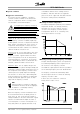
■ Temperature-dependent switch frequency
This function ensures the highest possible switch
frequency without the frequency converter becoming
thermally overloaded. The internal temperature is the
actual expression of the degree to which the switch
frequency can be based on the load, the ambient
temperature, the supply voltage and the cable length.
The function ensures that the frequency converter
automatically adjusts the switch frequency between f
sw,
min
and f
sw, max
(parameter 411), see drawing below.
When using the LC filter the minimum switch
frequency is 4.5 kHz.
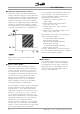
■ Galvanic Isolation (PELV)
PELV (Protective Extra Low Voltage) insulation is
achieved by inserting galvanic isolators between the
control circuits and circuits that are connected to
the mains potential. The VLT is designed to meet
the requirements for protective separation by means
of having the necessary creepage and clearance
distances. These requirements are described in
standard EN 50 178. It is also a requirement
that the installation is carried out as described in
local/national regulations regarding PELV.
All control terminals, terminals for serial communication
and relay terminals are safely separated from the
mains potential, i.e. they comply with the PELV
requirements. Circuits that are connected to control
terminals 12, 18, 19, 20, 27, 29, 33, 42, 46, 50,
53, 55 and 60 are galvanically connected to one
another. Serial communication connected to fieldbus
is galvanically insulated from the control terminals,
although this is only a functional insulation.
The relay contacts on terminals 1 - 3 are insulated
from the other control circuits with reinforced/double
isolation, i.e. PELV is observed for these, even though
there is mains potential at the relay terminals.
The circuit elements described below form the safe
electric separation. They fulfill the requirements
for reinforced/double insulation and associated
testing pursuant to EN 50 178.
1. Transformer and optical separation in
voltage supply.
2. Optical insulation between Basic Motor
Control and control card.
3. Insulation between the control card and
the power part.
4. Relay contacts and terminals relating to other
circuits on the control card.
PELV insulation of the control card is guaranteed
under the following conditions:
- TT network with maximum 300 Vrms
between phase and earth.
- TN network with maximum 300 Vrms
between phase and earth.
- IT network with maximum 400 Vrms
between phase and earth.
In order to maintain PELV all connections made to
the control terminals must be PELV, e.g. thermistor
must be reinforced/double insulated.
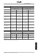
■ EMC emission
The following system results are achieved on
a system consisting of a VLT Series 2800 with
screened/armoured control cable, control box
with potentiometer, screened/armoured motor
cable and screened/armoured brake cable as
well as an LCP2 with cable.
MG.28.A9.02 - VLT is a registered Danfoss trademark
76