
Technical data

VLT
®
2800 Series
All about VLT
2800
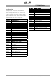
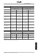
No. Description Warning Alarm Trip
locked
2 Live zero error (LIVE ZERO ERROR) X X X
4 Mains phase loss (MAINS PHASE LOSS) X X X
5 Voltage warning high (DC LINK VOLTAGE HIGH) X
6 Voltage warning low (DC LINK VOLTAGE LOW) X
7 Overvoltage (DC LINK OVERVOLT) X X X
8 Undervoltage (DC LINK UNDERVOLT) X X X
9 Inverter overload (INVERTER TIME) X X
10 Motor overloaded ( MOTOR, TIME) X X
11 Motor thermistor (MOTOR THERMISTOR) X X
12 Current limit (CURRENT LIMIT) X X
13 Overcurrent (OVERCURRENT) X X X
14 Earth fault (EARTH FAULT) X X
15 Switch mode fault (SWITCH MODE FAULT) X X
16 Short-circuit (CURR. SHORT CIRCUIT) X X
17 Serial communication timeout (STD BUS TIMEOUT) X X
18 HPFB bus timeout (HPFB TIMEOUT) X X
33 Out of frequency range (OUT FREQ RNG/ROT LIM) X
34 HPFB communication fault (PROFIBUS OPT. FAULT) X X
35 Inrush fault (INRUSH FAULT) X X
36 Overtemperature (OVERTEMPERATURE) X X
37-45 Internal fault (INTERNAL FAULT) X X
50 AMT not possible X
51 AMT fault re. nameplate data (AMT TYPE.DATA FAULT) X
54 AMT wrong motor (AMT WRONG MOTOR) X
55 AMT timeout (AMT TIMEOUT) X
56 AMT warning during AMT (AMT WARN. DURING AMT) X
99 Locked (LOCKED) X
LED indication
Warning yellow
Alarm red
Trip locked yellow and red
WARNING/ALARM 2: Live zero fault
The voltage or current signal on terminal 53 or
60 is below 50% of the preset value in parameter
309 or 315 Terminal, min. scaling.
WARNING/ALARM 4: Mains phase fault
No phase on mains supply side. Check the supply
voltage to the frequency converter. This fault is only
activein3-phasemainssupply. Thealarmcanalso
occur when the load is pulsing. In this instance the
pulses must be dampened, e.g. using an inertia disc.
WARNING 5: Voltage warning high
If the intermediate circuit voltage (UDC) is higher than
Voltage warning high the frequency converter will
give a warning and the motor will continue to run
unchanged. If the UDC remains above the voltage
warning limit, the inverter will trip after a set time. The
time depends on the device, and is set at 5 - 10
sec. Note: The frequency converter will trip with an
alarm 7 (overvoltage). A voltage warning can occur
when the connected mains voltage is too high. Check
whether the supply voltage is suitable for the frequency
converter, see Technical data. A voltage warning
can also occur if the motor frequency is reduced too
quickly due to ramp down time being too short.
WARNING 6: Voltage warning low
If the intermediate circuit voltage (UDC)
is lower than
Voltage warning low the frequency converter will give a
warning and the motor will continue to run unchanged.
A voltage warning can occur when the con
nected
mains voltage is too low. Check whether the supply
voltage is suitable for the frequency converter, see
Technical data. When the frequen
cy converter is
switched off a brief warning 6 (and warning 8) appears.
WARNING/ALARM 7: Overvoltage
If the intermediate voltage (UDC) goes over the
inverter’s Overvoltage lim
it the inverter will be switched
off until the UDC has once more fallen below the
overvoltage limit. If the UDC remains above the
overvoltag limit the inve
rter will trip after a set time.
The time depends on the device, and is set at 5
- 10 sec. An overvoltage in the UDC can occur
MG.28.A9.02 - VLT is a registered Danfoss trademark
71