vacon nx ac drives optcp profinet option board user manual
• vacon INDEX Document code: DPD00895A Last edited: 27.01.2012 1. Introduction ....................................................................................................................... 3 2. Ethernet board technical data ............................................................................................ 4 2.1. 2.2. 2.3. 2.4. 3. Installation ......................................................................................................................... 8 3.1. 3.2. 3.3.
Introduction vacon • 3 1. INTRODUCTION Vacon NX frequency converters can be connected to Ethernet using an Ethernet fieldbus board OPTCP. The OPTCP can be installed in board slots D or E. Every appliance connected to an Ethernet network has two identifiers; a MAC address and an IP address. The MAC address (Address format: xx:xx:xx:xx:xx:xx ) is unique to the appliance and cannot be changed.
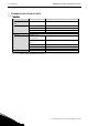
• vacon Ethernet board technical data 2. ETHERNET BOARD TECHNICAL DATA 2.1. Overview General Ethernet connections Communications Protocol Environment Board name Interface OPTCP RJ-45 connector Transfer cable Speed Duplex Default IP-address Profinet I/O Ambient operating temperature Storing temperature Humidity Altitude Vibration Shielded Twisted Pair (STP) CAT5e 10 / 100 Mb half / full 192.168.0.10 Safety –10°C…50°C –40°C…70°C <95%, no condensation allowed Max. 1000 m 0.
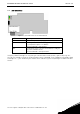
Ethernet board technical data vacon • 5 2.2. LED indications Figure 1-2, LED indications on the OPTCP board LED: H4 H1 H2 Meaning: LED in ON when board is powered Blinking 0.25s ON / 0.25s OFF when board firmware is corrupted (chapter 3.2.1 NOTE). OFF when board is operational. Blinking 2.5s ON / 2.5s OFF when board is ready for external communication. OFF when board is not operational. Using the "Node Flashing Test" function you can determine to which device you are directly connected.
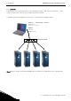
• vacon Ethernet board technical data 2.3. Ethernet Common-use cases of Ethernet devices are ‘human to machine’ and ‘machine to machine’. Basic features of these two cases are presented in the pictures below. 1. Human to machine (Graphical User interface, relatively slow communication) NCDrive / NCIPConfig interface -Parameter -Slow rate actual Values -Trends -Fault history Ethernet switch Note! NCDrive can be used in NXS and NXP drives via Ethernet. In NXL drives this is not possible. 2 Tel.
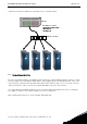
Ethernet board technical data vacon • 7 2. Machine to machine (Industrial environment, fast communication) PLC or Programmable Controller Master Real-Time Control Direction,... .. -Start/Stop, Direction, Reference -Feedback Ethernet switch 2.4. Connections and wiring The Ethernet board supports 10/100Mb speeds in both Full- and Half-duplex modes. However, using Profinet requires the Full-duplex mode and the 100-megabit speed.
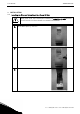
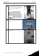
• vacon 3. Installation INSTALLATION 3.1. Installing the Ethernet Option Board in a Vacon NX Unit ! MAKE SURE THAT THE FREQUENCY CONVERTER IS SWITCHED OFF BEFORE AN OPTION OR FIELDBUS BOARD IS CHANGED OR ADDED! NOTE 2 A Vacon NX frequency converter. B Remove the cable cover. C Open the cover of the control unit. Tel.
Installation D Install EtherNet option board in slot D or E on the control board of the frequency converter. Make sure that the grounding plate (see below) fits tightly in the clamp. E Make a sufficiently wide opening for your cable by cutting the grid as wide as necessary. F Close the cover of the control unit and the cable cover. 24-hour support +358 (0)40 837 1150 • Email: fieldbus@vacon.
• vacon Installation 3.2. NCDrive NCDrive software can be used with the Ethernet board in NXS and NXP drives. NOTE! Does not work with NXL NCDrive software is recommended to be used in LAN (Local Area Network) only. NOTE! If OPTCI Ethernet Option board is used for NC Tools connection, like NCDrive, the OPTD3 board can not be used. NOTE! NCLoad does not work via Ethernet. See NCDrive help for further information 3.3.
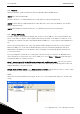
Installation vacon • 11 Step 3. Set names. Select the cell in column ‘Node’ and enter the name of the node. Step 4. Set IP addresses. Change the node’s IP settings according to the network IP settings. The program will report conflicts with a red color in a table cell. Step 5. Send configuration to boards. In the table view, check the boxes for boards whose configuration you want to send and select Configuration, then Configure. Your changes are sent to the network and will be valid immediately.
• vacon Installation After clicking the VCN packet field, a file open window where you can choose a new firmware packet is displayed. Select the desired packet and click Open. NOTE! Do not do a power up cycle after downloading the option board software or installing a new option board to the drive within 1 minute. This may cause the option board to go to “Safe Mode”. This situation can only be solved by re-downloading the software. The Safe Mode triggers a fault code (F54).
Installation 3.3.2. vacon • 13 Configure Option board parameters These features are available from NCIPConfig tool version 1.6. In the tree-view, expand the folders until you reach the board parameters. Slowly double-click the parameter (Comm. Time-out in figure below) and enter new value. New parameter values are automatically sent to the option board after the modification is complete.
• vacon Installation 3.4. Example with Siemens PLC 1. Create project 2. Insert station 2 Tel.
Installation 3. vacon • 15 Double-click hardware to open HW config window. 4. Insert rail 24-hour support +358 (0)40 837 1150 • Email: fieldbus@vacon.
• vacon Installation 5. Insert power supply 6. Insert CPU 2 Tel.
Installation vacon • 17 7. Change IP address and select subnet by clicking New. 8. Click OK 24-hour support +358 (0)40 837 1150 • Email: fieldbus@vacon.
• vacon Installation 9. Click OK 10. Now configuration should look like this 2 Tel.
Installation vacon • 19 11. Drag and drop OPTCP to Profinet IO system 12. Select communication profile 24-hour support +358 (0)40 837 1150 • Email: fieldbus@vacon.
• vacon Installation 13. Change Optioncard properties 2 Tel.
Installation vacon • 21 14. Verify Device Name. 15. Close window. 24-hour support +358 (0)40 837 1150 • Email: fieldbus@vacon.
• vacon Installation 16. Change IO cycle to 16 ms (minimum) or greater. 2 Tel.
Commissioning vacon • 23 4. COMMISSIONING The Vacon Ethernet board is commissioned with the control keypad by giving values to appropriate parameters in menu M7 (or with NCIPConfig tool, read chapter IP Tool NCIPConfig). Keypad commissioning is only possible with NXS and NXP series AC drives. AC drives of the NXL series can only be commissioned with the NCIPConfig tool. 4.1.
• vacon Commissioning NOTE! If the fieldbus cable is broken at the Ethernet board end or removed a fieldbus error is immediately generated. All Ethernet parameters are saved to the Ethernet board (not to the control board). If the Ethernet board is replaced by a new one you must re-configure the new Ethernet board. Option board parameters can also be saved to the keypad using the NCIPConfig tool or the NCDrive. 4.4.
Profinet IO vacon • 25 5. PROFINET IO PROFINET is the Ethernet-based automation standard of PROFIBUS International for the implementation of an integrated and consistent automation solution based on Industrial Ethernet. PROFINET supports the integration of simple distributed field devices and time-critical applications in (switched) Ethernet communication, as well as the integration of component-based distributed automation systems for vertical and horizontal integration of networks. 5.1.
• vacon 5.1.1. Profinet IO Control word (Vendor profile) The Control command for the state machine (see Figure 2) The state machine describes the device status and the possible control sequence of the frequency converter.
Profinet IO 5.1.2. vacon • 27 Status word (Vendor profile) Information about the status of the device and messages is indicated in the Status word. The Status word is composed of 16 bits that have the following meanings: Bit 0 1 2 3 4 5 6 7 8 9 10 11 12 13 14 15 Description Value = 0 Not Ready (initial) Not Ready DISABLE NO FAULT STOP 2 STOP 3 START ENABLE No Warning Reference ≠ Actual value Fieldbus control OFF Not used Not used FC stopped FC not ready Not used Not used Table 4.
• vacon 5.1.3. Profinet IO State Machine The state machine describes the device status and the possible control sequence of the frequency converter. The state transitions can be generated by using the “Control word”. The “Status word” indicates the current status of the state machine. The modes INIT, STOP, RUN and FAULT correspond to the actual mode of the Frequency converter. NOTE! Always set CW bit0 to 0 after fault reset before proceeding! Figure 2. 2 Tel.
Profinet IO 5.1.4. vacon • 29 Reference This is the reference 1 to the frequency converter. Used normally as Speed reference. The allowed scaling is –10000...10000. In the application, the value is scaled in percentage of the frequency area between set minimum and maximum frequency. -10000 = 100,00 % 0 = 0,00 % 10000 = 100,00 % 5.1.5. (Direction reverse) (Direction forward) (Direction forward) Actual value This is the actual value from the frequency converter. Value between -10000...10000.
• vacon Profinet IO 5.2. Bypass profile In BYPASS mode there are three types. Descriptions CW SW REF ACT PD 5.2.1. Byte Control Word Status Word Reference value Actual value Process Data Control Word (Bypass profile) The meanings of the Control Word bits is application-dependent. 5.2.2. Status Word (Bypass profile) The meanings of the Status Word bits are application-dependent. 2 Tel.
Profinet IO vacon • 31 5.3. Profidrive profile Process Data field STW1 NSOLL_A PDI1 PDI2 PDI3 PDI4 PDI5 PDI6 PDI7 PDI8 ZSW1 NIST_A PDO1 PDO2 PDO3 PDO4 PDO5 PDO6 PDO7 PDO8 std telegram 1 std telegram 1 + 1pd std telegram 1 + 2pd std telegram 1 + 3pd std telegram 1 + 4pd std telegram 1 + 5pd std telegram 1 + 6pd std telegram 1 + 7pd std telegram 1 + 8pd The PROFIDRIVE profile has been jointly defined by drive manufacturers.
• vacon Bits Profinet IO Description Value = 0 Value = 1 0 OFF ON 1 Coast stop (No OFF2 / OFF2) No coast stop 2 Quick stop (No OFF3 / OFF3) No quick stop 3 Disable operation Enable operation 4 Reset ramp generatorb Enable ramp generatorb 5 Freeze ramp generatorb Unfreeze ramp generatorb 6 Disable setpoint Enable setpoint 7 Fault acknowledgement (0->1) 8 Jog 1 OFFa Jog 1 ONa 9 Jog 2 OFFa Jog 2 ONa 10 No control by PLC Control by PLC 11 Device-specific 12-15 Device-specific a Optional; depends on appli
Profinet IO 5.3.1.3. vacon • 33 NSOLL_A NSOLL_A is the reference to the drive. It is used normally as Speed reference. Reference is a 16-bit word containing a sign bit and a 15-bit integer. A negative reference (indicating reversed direction of rotation) is formed by calculating the two’s complement from the corresponding positive reference. The allowed scaling is –10000...10000. In the drive application, the value is scaled in percentage of the frequency area between set minimum and maximum frequency.
• vacon 5.3.1.5. Profinet IO State Machine The state machine describes the device status and the possible control sequence of the frequency converter. The state transitions can be generated by using the “Control word”. The “Status word” indicates the current status of the state machine. The modes INIT, STOP, RUN and FAULT correspond to the actual mode of the Frequency converter General state diagram Power ON Coast Stop S1: Switching On Inhibited a STW1 bit1=False ZSW1 bit 6 = True; 0,1,2,”p.
Profinet IO vacon • 35 5.4. Parameter channel The Parameter channel can be used to access the Drive’s parameters and the PROFIDRIVE’s parameters.
• vacon Profinet IO It is possible to read and write parameters from and to the drive. In order to process them through the Base Mode Parameter Access mechanism, you should: o set requested PNU to 10001 (0x2711) o set requested subindex with the drive parameter ID NOTE: Parameters which are read from the drive have always the format set to “Word” – 0x42.
Profinet IO vacon • 37 PROFIDRIVE’s profile-specific parameters PNU 922 930 944 947 950 964 965 975 980 to 989 Signification Telegram Selection Operating Mode Fault Message Counter Fault Number Scaling of the Fault Buffer Drive Unit Identification Profile Identification Number DO Identification Datatype Number List of Defined Parameter Request Header, Meaning of the fields Field Request Reference Request ID DO-ID Number of Parameters Attribute Number of Elements Parameter Number Subindex Format Numbe
• vacon Profinet IO Response Header, Meaning of the fields 2 Field Request Reference Response ID Meaning Mirrored from request. Slave’s response. DO-ID Number of Parameters Format Mirrored from request. Number of parameters in response. Number of Values Value Number of values in response. Value of request. Data type of response value.
Profinet IO vacon • 39 5.5. Parameter data transfer examples Reading parameter: Request parameter value, single: Request Header Parameter Address 05 01 01 01 10 01 27 11 05 = Request Reference 01 = Request ID 01 = DO-ID 01 = No. of parameters 10 = Attribute 01 = No. of elements 2711 = Parameter number (0x2711 Request Drive Parameters) 0065 = Subindex (0x65 = ID 101 Min Frequency) Response: Request Header 05 01 05 = Request Reference. Mirrored 01 = Request ID 01 = DO-ID. Mirrored 01 = No.
• vacon APPENDIX 6. APPENDIX Process Data OUT (Slave Master) The fieldbus master can read the frequency converter’s actual values using process data variables.
APPENDIX vacon • 41 Multipurpose control application Data Reference ControlWord Process Data IN1 Process Data IN2 Process Data IN3 PD3 – PD8 Value Speed Reference Start/Stop Command Fault reset Command Torque Reference Free Analogue INPUT Adjust Input Not Used Unit % - Scale 0.01% - % % % - 0.1% 0.01% 0.01% - Unit % - Scale 0.01% - % 0.01% % 0.01% % 0.
• vacon APPENDIX License for LWIP Copyright (c) 2001, 2002 Swedish Institute of Computer Science. All rights reserved. Redistribution and use in source and binary forms, with or without modification, are permitted provided that the following conditions are met: 1. Redistributions of source code must retain the above copyright notice, this list of conditions and the following disclaimer. 2.
Find your nearest Vacon office on the Internet at: www.vacon.com Manual authoring: documentation@vacon.com Vacon Plc. Runsorintie 7 65380 Vaasa Finland Subject to change without prior notice © 2012 Vacon Plc. Document ID: Rev.