
User manual
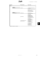


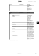


Main Menu Horizontal menu Page content
[0] Setup
↳
Submenu
[0] Calibration [0] Sensors [0] Irradiation sensor scale: mV
(1000 W/m
2
)
[0] Irradiation sensor temp. coeff.:
%/°C
[0] PV temp offset: 2 °C
[0] Ambient temp offset: °C
[0] S0 scale: pulses/kWh
[0] PV Array
[0] PV1 Array area: m
2
[0] PV1 Array power: W
[0] PV2 Array area: m
2
[0] PV2 Array power: W
[0] PV3 Array area: m
2
[0] PV3 Array power: W
[0] Environment Here the values for CO
2
emission
and revenue calculation are en-
tered.
[0] Communication [0] RS485 Setup [0] Network:
[0] Subnet:
[0] Address:
[0] IP Setup [0] Configuration Automatic/man-
ual
[0] IP address:
[0] Subnet mask:
[0] Default gateway:
[0] DNS Server:
[0] Remote access [2] Change functional safety set-
ting:
[0] External Alarm [0] Alarm: Enable/Disable
[0] Alarm timeout
[0] Stop alarm
[0] Test alarm
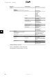
[0] Inverter details [0] General [0] Inverter name:
[0] Group name:
[0] Master mode:
[0] List of follower inverters
[1] Date and time [1] Time:
[1] Date:
[1] Time zone:
[1] Reset max values Reset the max values of the inver-
ter
[0] Logging [0] Logging interval:
[0] Logging capacity:
[1] Delete event log
[1] Delete Production log
[1] Delete Energy log
[1] Delete irradiation log
[0] Messaging [0] Enable/disable messaging for
the individual inverter
[0] Security Change the current security level
of the inverter.
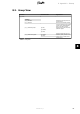
[0] Setup details [0] Setup details [0] Language:
[2] Country
3
:
[2] 10 min mean
3
[2] 10 min. mean voltage: V
[2] Time to disconnect: ms
[2] ROCOF
3
[2] ROCOF limit: Hz/s
[2] Time to disconnect: ms
[1] PV Configuration PV Configuration, individual or par-
allel
[1] PV 1 configuration
[1] PV 2 configuration
[1] PV 3 configuration
1
[1] Force inverter power up Turns on grid supply to the control
board.
Table 8.10: Inverter View - Continued
8. Appendix A - Sitemap
66 L00410583-01_02
8